


25
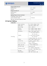
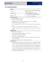
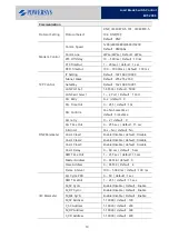
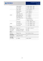
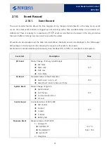
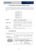
Load Break Switch Control
ERT-200S
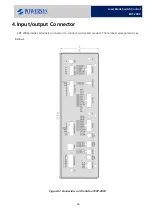
The Load Break Switch is connected to the controller by thecontrol cable. The cable plugs into compatible
ports at both the controller and underside of the switch.
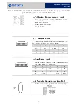
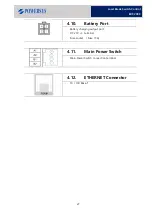
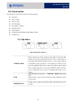
4.1.
Modem Power supply Input
-
Power supply connecter has ERT-200Sexternal modem
power supply terminal.
-
Modem power Fuse socket
-
DC 12V (Options)
4.2.
Current Input
-
Current connecters with phase A and follows by B, C, N.
Aux1, Aux2 is spare Aux Port and not assign.
1
2
3
4
ZCT2
ZCT1
SPARE
SEF
5
6
7
8
IN
IC
IB
IA
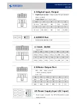
4.3.
Voltage Input
-
Voltage connector has source side 3 phases(A,B,C) and
load side 3 phases(R,S,T) as bellows;
1
2
3
4
5
VT
VS
VR
VC
VB
6
7
8
9
10
VA
V_COM
GND
24Vdc
4.4.
Remote Communication Port
-
Modem communication port is D-SUB 9 pin male type
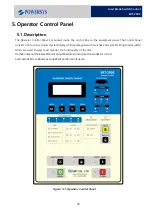
Summary of Contents for ERT-200S
Page 1: ...Feeder Remote terminal Unit ERT 200S Manual www powersys kr...
Page 13: ...13 Load Break Switch Control ERT 200S 2 5 Function BlockDiagram...
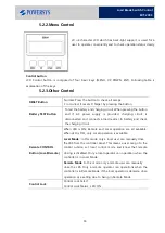
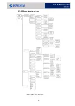
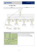
Page 38: ...38 Load Break Switch Control ERT 200S 5 3 3 Menu structure tree Figure Menu Tree Structure...
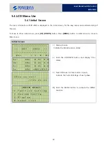
Page 42: ...42 Load Break Switch Control ERT 200S...
Page 96: ...Appendix 1 Drawings 1 Enclosure Control Cabinet...