background image


15 

INSTALLATION OF BARRIER ARM 


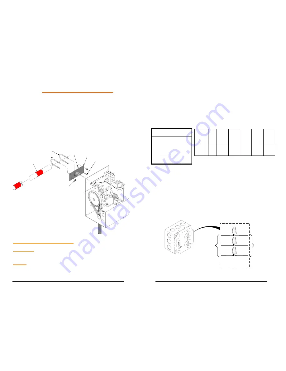
1. Install arm flange on power head output shaft as shown 

figure below ,and secure position with ¼” square key and 
(2) 5/16 set screws. 


2. Install (2) 2-1/2” U-bolts in arm flange as shown. 


3. Install 3/8 serrated flange nuts loosely on U- bolts. 


4. Insert barrier arm pipe through two U-bolts and secure the 

desired position by tightening the 3/8 serrated flange nuts 
on the u-bolts. 


2-1/2" U-BOLTS

ARM FLANGE

POWER HEAD

OUTPUT SHAFT

1/4" SQUARE KEY

5/16" SET

SCREWS 

(4) 3/8" SERRATED

FLANGE NUTS 

BARRIER ARM PIPE


ELECTRICAL CONNECTIONS 


WARNING

- DO NOT APPLY POWER UNTIL TOLD TO DO 

SO. RISK OF SHOCK OR INJURY MAY RESULT! 


NOTE:


Wiring to operator must use watertight materials in 

accordance with local electric code. See wire gauge/distance 
charts for proper sizing.  Master/Slave installations should 
have 

SEPARATE

 power supply wiring or length of wire runs 


16 

BLK

BLK

WHT

WHT

GRN

GND

INSIDE UTILITY BOX,

CONNECT AS SHOWN

INCOMING
POWER

115V - 1Ø

OPERATOR

UTILITY BOX

should be figured at half that shown on the chart. 

This unit 

must be grounded in accordance with N.E.C. and local 
codes. 

Before connecting the operator, use a voltmeter to determine 
that the electrical service is 115V. THIS OPERATOR 
CANNOT BE CONNECTED AT 230 VOLTS. Damage will 
result which is not covered under warranty.


1.  Be sure power switches at source and operator are OFF. 
 
2.  Connect incoming power lines and ground wire as shown 

below. 


Hot leg (black) to BLACK; Neutral (white) to White: 
Ground to GREEN 


Line 

Voltage

  HP 

14 

AWG 

12 

AWG 

10 

AWG 

AWG 

 
   6 
AWG 


115 

VAC 

1/2 

150 250 400 500 650 

LOW   VOLTAGE  WIRE

GAUGE /DISTANCE  CHART

24 AWG:      Up to 150'

 20 AWG:      150' - 200'

                        250' - 1,500'

Control wiring should be run as twisted

pairs. DO NOT run control wires in the

same conduit as power wires. telephone

wires, or loop detector leads.

18 AWG:

Summary of Contents for MBG

Page 1: ...Installation of Power Head 14 Installation of Barrier Arm 15 Electrical Connections 15 Left Hand Right Hand Conversions 17 Manual Operation 18 Limit Adjustment Procedure 19 Master Slave Operation 20 C...

Page 2: ...mation provided to help ensure safe system design installation and use WARNING Gate operators are only one part of a TOTAL GATE OPERATING SYSTEM It is the responsibility of purchaser designer and inst...

Page 3: ...ate if the automatic controls do not work Locate the pushbutton or key switch and small warning placard within sight of the gate in a secured area at least 10 feet or more from the gate and fence to k...

Page 4: ...hen LEAVE A COPY OF THIS BROCHURE WITH THE END USER 8 END USER SAFETY WARNINGS Be sure you ve been fully instructed on the sequence of operation for your specific gate system s Keep the gate properly...

Page 5: ...ate any controls without watching the movement of the gate 7 Be sure the gate arm DOES NOT come within 2 feet of any rigid object therefore causing an entrapment situation 10 2 FEET 8 If your gate clo...

Page 6: ...Allow at least 2 feet clearance from rigid objects to gate arm 12 INSTALLATION OF MOUNTING PIPE N o t e T h e r e a r e t w o o p t i o n s f o r t h e i n s t a l l a t i o n o f a m o u n t i n g p...

Page 7: ...EAD 1 Remove exterior cover and install 2 2 U bolts as shown below 2 Install 3 8 flat washers 3 8 lock washers and 3 8 nuts 3 Mount power head on top of pipe by inserting pipe up through large hole in...

Page 8: ...ave installations should have SEPARATE power supply wiring or length of wire runs 16 BLK BLK WHT WHT GRN GND INSIDE UTILITY BOX CONNECT AS SHOWN INCOMING POWER 115V 1 OPERATOR UTILITY BOX should be fi...

Page 9: ...UAL OPERATION WARNING TURN OFF POWER SUPPLY BEFORE REMOVING COVER 1 Remove 4 cover mounting screws and lift off top cover 2 Remove crank pin from storage area in drive frame See Diagram Note This will...

Page 10: ...w 4 Remove crank pin from timing pulley and replace in storage area on drive frame Note Be sure drive pin is fully inserted back into drive frame in order to activate interlock 5 Turn on power then ra...

Page 11: ...TIMER TO CLOSE OPTION The operator is equipped with a timer to close option for use with OPEN ONLY control devices such as a radio control or card key control The AUTO RECLOSE TIMER adjustment screw i...

Page 12: ...the gate if closing 3 The CLOSE LOOP provides a signal to close the gate when a vehicle exits the loop LOOP INSTALLATION 1 Layout the desired loop locations per the diagram The standard size chart at...

Page 13: ...or for available sealants 7 Mount the loop detector in the operator and connect the wire loop 26 8 Connect loop detector to the control board as shown in the following diagrams Note The following diag...

Page 14: ...t Used OR BK WH R GR BR GY TO DRIVEWAY LOOP NOTE TWIST LEADS APPOX 6 TURNS PER FOOT 1 2 3 4 5 6 7 8 9 A B CLOSE LOOP CONNECTION WARNING LOOP DETECTOR MUST BE PROGRAMMED TO ACTIVATE OPERATOR WHEN VEHIC...

Page 15: ...___ ______________________________________________ ______________________________________________ 30 _____________________________________________ Notes ______________________________________________...

Page 16: ...charges incurred in connection with the installation of warranted parts In order to activate this warranty the registration form on opposite page MUST be completed and returned within THIRTY CALENDER...

Reviews: