Alutech Levigato LG Series, Assembly And Operation Manual
The Alutech Levigato LG Series is a cutting-edge product that guarantees high-quality performance. To get the most out of your purchase, make sure to download the free Assembly And Operation Manual from our website, offering you step-by-step instructions for seamless installation and operation.
Share
Download


Reviews:
No comments
Related manuals for Levigato LG Series

200/BLA24L
Brand: Cardin Elettronica Pages: 28

PERSA 400
Brand: Motorline professional Pages: 14
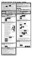
INTELLICODE 1
Brand: GMI Pages: 2

500A series
Brand: Byan Pages: 29

LM22N
Brand: CAME Pages: 12

Cardin SLX Series
Brand: Riello Elettronica Pages: 36

SPEED
Brand: tau Pages: 36

R18 series
Brand: tau Pages: 32

1RM D Series
Brand: HYDOM Pages: 12
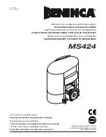
MS424
Brand: Beninca Pages: 24

Kinetic 1
Brand: Wallace Perimeter Security Pages: 130

cyborg Panther 1200
Brand: Accessmatic Pages: 60

GI.BI.DI. DSK40
Brand: Bandini Industrie Pages: 14

9100
Brand: Waync Dalton Pages: 40

Navigator 2245RGD
Brand: Raynor Pages: 36

Whisper Drive Security+ 459950
Brand: Chamberlain Pages: 88

Ultra S
Brand: ABON Pages: 80

Blank
Brand: Gate Motors Pages: 4


