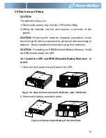
16
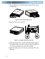
Figure 3-13. Install the sliding rails
7. For 10K---Install the battery pack and battery protection plate,
then replace the front panel.
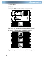
Figure 3-14. Installing the Cabinet
8. For 6K---Replace the battery tray, and connect the internal
battery connector, then replace the protection plate and the front
panel.
9. If installing additional UPSs, repeat from Step 1 to Step 8 for
each cabinet.
3.5.2 Installing the EBMs
Note: A little of arcing may occur when connecting an EBM to the
UPS. That is normal and not harmed. Plug the EBM cable into the
UPS battery connector quickly and firmly.
Summary of Contents for VFI 10000P/RT LCD
Page 4: ......
Page 31: ...27 Figure 4 5 a Parallel systerm wiring diagram of 6K 10K ...
Page 32: ...28 Figure 4 5 b Parallel System Installation Diagram ...
Page 43: ...39 Figure 5 14 Main menu tree ...
Page 50: ...46 Example set rated output voltage value Figure 5 20 Set rated output voltage value ...


