15
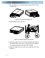
3. Pull the battery tray out using the plastic tabs and then remove
the battery tray.
Figure 3-11: Removing the Battery Tray
4. Install the PDU’s ears to the UPS
Figure 3-12. Install the PDU’s ears to the UPS
5. Select the proper holes in the rail for positioning the cabinet in
the desired location in the rack. Locate the rails at the bottom of
the 3U space allocated for the each UPS and EBM.
6. Install the sliding rails in the rack, then install the UPS in the
sliding rail.
Summary of Contents for VFI 10000P/RT LCD
Page 4: ......
Page 31: ...27 Figure 4 5 a Parallel systerm wiring diagram of 6K 10K ...
Page 32: ...28 Figure 4 5 b Parallel System Installation Diagram ...
Page 43: ...39 Figure 5 14 Main menu tree ...
Page 50: ...46 Example set rated output voltage value Figure 5 20 Set rated output voltage value ...


