8785115
200A Multi-Process Welder with LCD Display
V4.0
38
For technical questions call 1-800-665-8685
This prevents the tungsten tip sticking to the workpiece
and breaking the tip from the tungsten electrode. It is a
simple, safe lower cost alternative arc ignition process to
HF (high frequency) and a superior arc start process to
scratch start. There is a particular technique called
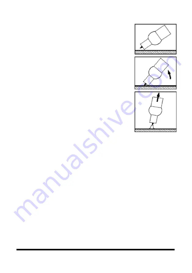
‘rocking the cup’ used in the Lift Arc process that
provides easy use of the Lift Arc function.
1. Open the gas cylinder valve and set the flow
between 21 to 30 CFH.
2. Set the welding current.
3. Make sure the front end parts of the TIG torch are
correctly assembled, use the correct size and type of
tungsten electrode for the job, the tungsten electrode
requires a sharpened point for DC welding.
4. Lay the outside edge of the Gas Cup on the
workpiece with the Tungsten Electrode 1/16 in. from
the workpiece.
5. With a small movement, rotate the Gas Cup forward
so that the Tungsten Electrode touches the workpiece
.
6. Now rotate the gas cup in the reverse direction to lift the tungsten
electrode from the workpiece to create the arc.
TIG WELDING FUSION TECHNIQUE
Manual TIG welding is often considered the most difficult of all the welding
processes. Because the welder must maintain a short arc length, great care and skill
is required to prevent contact between the electrode and the workpiece. Similar to
Oxygen Acetylene torch welding, TIG welding normally requires two hands and in
most instances requires the welder to manually feed a filler wire into the weld pool
with one hand while manipulating the welding torch in the other.
However, some welds combining thin materials can be accomplished without
filler metal like edge, corner and butt joints. This is known as fusion welding
where the edges of the metal pieces are melted together using only the heat and
arc force generated by the TIG arc. Once the arc is started the torch tungsten is
held in place until a weld pool is created, a circular movement of the tungsten
will assist is creating a weld pool of the desired size. Once the weld pool is
Fig. 18


