


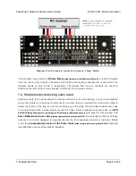


• The
battery level jumper
connects the Arduino’s analog pin 1 to a voltage divider circuit that
allows you to monitor the Zumo’s battery voltage. This jumper is disconnected by default and
can be connected by soldering a short length of wire between the two holes.
The divider outputs a voltage equal to two-thirds of the battery voltage, which will always be safely
below the Arduino’s maximum analog input voltage of 5 V. For example, at a battery voltage of 4.8 V,
analog pin 1 will be at a level of 3.2 V. Using Arduino’s
analogRead()
function, where 5 V is read as a
value of 1023, 3.2 V is read as a value of 655. To convert it back to the actual battery voltage, multiply
this number by 5000 mV×3/2 and divide by 1023:
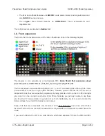
• The
buzzer control jumper
connects one of the Arduino’s PWM outputs to the buzzer on the
Zumo Shield. This jumper is disconnected by default on both the assembled and kit versions
of the Zumo robot; it must be connected to enable the buzzer.
If you have an Arduino
Uno
or an older Arduino (with an ATmega328P or ATmega168 microcontroller),
you should jumper the two holes bracketed with the label
328P
to connect the BZ pin to digital pin 3.
If you have an
A-Star 32U4 Prime
or Arduino
Leonardo
, you should jumper the two holes bracketed
1
unsigned
int
batteryVoltage = analogRead(1) * 5000L * 3/2 / 1023;
Pololu Zumo Shield for Arduino User’s Guide
© 2001–2019 Pololu Corporation
3. The Zumo Shield in detail
Page 35 of 52


