


6.
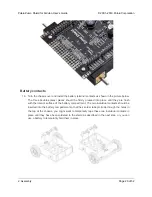
Optional:
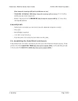
At this point, you might consider soldering additional components (such as
sensors), or headers or wires for connecting them, to the shield. If you do this, please check
to make sure your part placement does not interfere with the shield’s ability to mate with the
Arduino or the chassis. In particular, note that only components in the outermost three rows
of the front expansion area can extend below the board (the fourth front-expansion row can
only be used for pins extending above the board), and if you add any through-hole parts to
the prototyping areas on the shield, you will need to drill corresponding holes in the acrylic
spacer plate for the leads to fit into.
Motors and drive sprockets
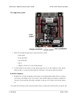
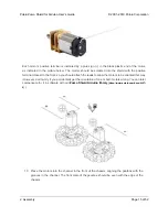
7. Press the output shafts of the motors into the drive sprockets, with the raised lip on one side
of the sprocket facing away from the motor (as shown below). The end of the gearbox shaft
should end up flush with the outside of the sprocket. A good way to do this is to set the wheel
on flat surface (like a table top) and press the motor shaft into the wheel until it contacts the
surface.
Pololu Zumo Shield for Arduino User’s Guide
© 2001–2019 Pololu Corporation
2. Assembly
Page 13 of 52


