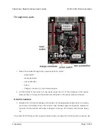


Assembling the sensor array
The Zumo reflectance sensor array ships with all
of the components you need to connect it to a
Zumo shield:
• sensor array PCB with the surface-
mount parts pre-populated
• 2×12 extended 0.1″ male header (will
be soldered to sensor PCB)
• 2×12 0.1″ female header (will be
soldered to Zumo shield)
• 1×3
0.1″
straight
male
header
(optionally soldered to sensor PCB)
• 1×3 0.1″ right-angle male header
(optionally soldered to sensor PCB)
• blue shorting block
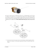
Before soldering in the main male header strip, we recommend soldering one of the two included
1×3 male headers into the set of three holes along the edge of the board. This step is optional but
recommended because it allows dynamic control of the IR emitters (and red LEDs). By controlling
when these LEDs are on, you can save power and make your programs easier to debug. If you skip
this step, the IR emitters will just be on whenever the sensor array is plugged in and the Zumo is on.
Pololu Zumo Shield for Arduino User’s Guide
© 2001–2019 Pololu Corporation
2. Assembly
Page 24 of 52


