


The reflectance sensor array features two visible (red) LEDs in series with the IR emitter
LEDs, so you can use the red LEDs to tell when the emitters are on and off.
Array pinout
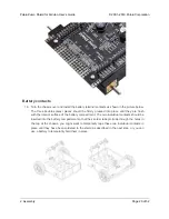
The Zumo reflectance sensor array gets all the necessary power and I/O connections from the 12
header pins that are circled on the silkscreen:
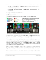
The default I/O connections are to pins that are otherwise unused by the Zumo shield. The shield uses
one digital I/O pin for each sensor (5, A2, A0, 11, A3, and 4), and if you add the LEDON shorting block,
one additional pin (either A4 or 2) is used. To configure the
ZumoReflectanceSensorArray
object to use
this default pinout, simply call
init
with no arguments:
If you opt to leave off the LEDON shorting block, you should use the
QTR_NO_EMITTER_PIN
initialization
parameter:
reflectanceSensors.init(QTR_NO_EMITTER_PIN)
. Otherwise, the library code will still be
trying to do something with the emitter pin (A4 or 2, depending on which Arduino you
are using), and this would interfere with your being able to use that pin for alternate
purposes.
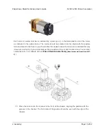
When soldering the male 2×12 header to the sensor array, you only need to solder those pins that
you will be using. If you solder all 24 pins, the sensor array will be connected to additional pins from
the Zumo shield’s front expansion area, though the array does not do anything with them in its default
configuration:
1
reflectanceSensors.init();
Pololu Zumo Shield for Arduino User’s Guide
© 2001–2019 Pololu Corporation
2. Assembly
Page 27 of 52


