


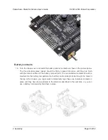


edge of the shield, which can be used to recharge the Zumo’s batteries without removing them from
the chassis. The positive pin of the charge connector, on the left, is indicated by a plus sign (+). A
charger like the
[https://www.pololu.com/product/2588]
, connected by clipping its alligator clips
to a pair of jumper wires inserted into the charge connector, works well for charging the Zumo.
After passing through reverse protection, the battery voltage is connected to the rest of the shield by
the power switch. The switched battery voltage is designated VBAT and provides power to the motors
through the DRV8835 motor driver. An on-board boost regulator, also supplied from VBAT, generates
7.45 V to power the Arduino through its Vin pin. In turn, the Arduino’s regulated 5V and 3.3V voltages
supply power to the motor driver logic, buzzer circuit, and compass module on the Zumo Shield.
Warning:
When powering the Arduino from the Zumo Shield, you must never connect a
different power supply to the Arduino’s VIN pin or plug a power supply into the Arduino’s
power jack, as doing so will create a short between the shield’s power supply and the
Arduino’s power supply that could permanently damage both the Arduino and the Zumo
Shield.
When the Arduino is connected to a computer via USB, it will receive power (and supply
5V and 3.3V to the shield) even when the Zumo Shield’s power switch is off. This can be
useful if you want to test your Arduino program without allowing the motors to run, since
turning the power switch off disconnects motor power (VBAT).
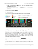
LEDs
There are five LEDs on the Zumo Shield:
• A set of power LEDs, one
blue
and one
red
, is located in each of the two rear corners of the
shield.
• A
yellow
user LED is located on the right edge of the shield. It is connected to
digital pin 13
on the Arduino, in parallel with the Arduino’s onboard user LED.
Pushbuttons
Two pushbuttons can be soldered to the Zumo Shield:
• The
reset pushbutton
is located on the left edge of the shield. It is connected to the
Arduino’s RESET pin and can be pressed to reset the Arduino.
• The
user pushbutton
is located on the rear edge of the shield. It is connected to
digital
pin 12
on the Arduino; pressing the button pulls the pin low, and we recommend enabling
Pololu Zumo Shield for Arduino User’s Guide
© 2001–2019 Pololu Corporation
3. The Zumo Shield in detail
Page 31 of 52


