


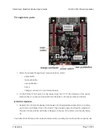


Jumpers and additional connections
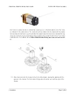
5.
Optional:
If you want to enable the buzzer, enable the battery level input, or disable the
compass, now is a good time to add and/or cut jumper connections to configure the shield to
your liking. This can also be done later, though soldering to these pins is more difficult once
the robot is assembled (especially if you decide later you want to add header pins for use
with shorting blocks; this would require a lot of disassembly). The jumpers are explained in
detail in
. The buzzer and battery level jumpers can be connected by soldering
in a short piece of wire between the two holes, while the compass I²C connections can be
broken by cutting the trace on the top of the board between the holes.
Note:
there is not
enough clearance to use male headers on the battery level and compass I²C jumpers if you
are using an Arduino with a DIP (through-hole) microcontroller.
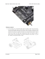
Instead of making a wire connection, you can solder a 1×3 male header to the buzzer
jumper holes to allow the use of a shorting block for connecting the buzzer. You can
also use male headers and shorting blocks for the battery level jumper and compass
jumpers if you have an Arduino Uno with an SMD (surface mount) microcontroller,
Arduino Leonardo, or A-Star 32U4 Prime. However, there is not enough clearance to use
male headers on the battery level and compass I²C jumpers if you are using an Arduino
with a DIP (through-hole) microcontroller.
Pololu Zumo Shield for Arduino User’s Guide
© 2001–2019 Pololu Corporation
2. Assembly
Page 12 of 52


