Connecting your equipment
03
34
En
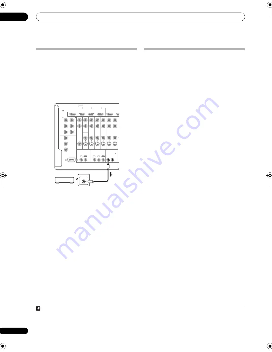
Switching components on and off using
the 12 volt trigger
You can connect com
p
onents in you
r
system (such as a
sc
r
een o
r
pr
ojecto
r
) to this
r
eceive
r
so that they switch on
o
r
off using 12 volt t
r
igge
r
s when you select an in
p
ut
function. Howeve
r
, you must s
p
ecify which in
p
ut
functions switch on the t
r
igge
r
using the
The Input Setup
menu
on
p
age 40. Note that this will only wo
r
k with
com
p
onents that have a standby mode.
1
•
Connect the 12 V TRIGGER jack of this receiver to
the 12 V trigger of another component.
Use a cable with a mono mini-
p
lug on each end fo
r
the
connection.
• The t
r
igge
r
maximum
p
owe
r
is DC OUT 12 V/50 mA.
Afte
r
you’ve s
p
ecified the in
p
ut functions that will switch
on the t
r
igge
r
, you’ll be able to switch the com
p
onent on
o
r
off just by
pr
essing the in
p
ut function(s) you’ve set on
p
age 40.
Connecting a PC for Advanced MCACC
output
When using Auto MCACC (
p
age 72) o
r
Acoustic
Calib
r
ation EQ P
r
ofessional (
p
age 77) to calib
r
ate the
r
eve
r
b cha
r
acte
r
istics of you
r
listening
r
oom, the 3D
g
r
a
p
hs of the
r
eve
r
b cha
r
acte
r
istics in you
r
listening
r
oom (befo
r
e and afte
r
calib
r
ation) can be checked on a
com
p
ute
r
sc
r
een by connecting the
r
eceive
r
to the
com
p
ute
r
and using a s
p
ecial a
pp
lication to t
r
ansfe
r
the
data. The va
r
ious MCACC
p
a
r
amete
r
s can also be
checked on the com
p
ute
r
.
Use a comme
r
cially-available RS-232C cable to connect
the RS-232C jack on you
r
com
p
ute
r
to the 9-
p
in RS-232C
jack on the back
p
anel of this
r
eceive
r
(the cable must be
c
r
oss ty
p
e, female–female).
The softwa
r
e to out
p
ut the
r
esults is available f
r
om the
su
pp
o
r
t a
r
ea of the Pionee
r
website (htt
p
://
www.
p
ionee
r
.eu). Inst
r
uctions fo
r
using the softwa
r
e a
r
e
also available he
r
e. If you have any questions about the
softwa
r
e,
p
lease contact the Pionee
r
Se
r
vice Cente
r
s
p
ecified on you
r
wa
rr
anty ca
r
d.
Please make su
r
e you
r
system meets the following
r
equi
r
ements:
• The com
p
ute
r
must be a PC functioning with one of
the following o
p
e
r
ating systems: Mic
r
osoft
®
Windows
®
Vista Home Basic/Home P
r
emium/
Ultimate SP1, Windows
®
XP P
r
ofessional/Home
Edition SP3 o
r
Windows
®
2000 P
r
ofessional SP4.
• The monito
r
must have a dis
p
lay
r
esolution of 800 x
600 dots (SVGA) o
r
g
r
eate
r
.
• The com
p
ute
r
must be equi
pp
ed with at least one RS-
232C
p
o
r
t.
2
• System must have inte
r
net access.
Microsoft
®
, Windows
®
Vista, Windows
®
XP and Windows
®
2000 are
either registered trademarks or trademarks of Microsoft Corporation in
the United States and/or other countries.
Note
1 T
r
igge
r
ed connections with u
p
to two devices com
p
atible with 12-volt t
r
igge
r
s can be made with this
r
eceive
r
.
RS-232C
COMPONENT
VIDEO
HDMI
ZONE2
VIDEO
S-VIDEO
ASSIGNABLE
ASSIGNABLE
MONITOR
OUT
MONITOR
OUT
IN
Y
L
R
P
B
P
R
Y
P
B
P
R
Y
OUT
DVD
IN
TV/SAT
IN
VIDEO
DVR
IN
IN
OUT
ZONE3
OUT
P
B
P
R
1
IN
BD IN
1
IN
2
IN
OUT 1
OUT
(KURO
LINK)
3
1
3
(DVD)
IN
2
(DVR)
CONTROL
IR
12 V TRIGGER
IN
IN
IN
OUT
OUT
1
2
1
2
(OUTPUT 12 V
TOTAL 50 mA MAX)
12 V TRIGGER
INPUT
2 La
p
to
p
s and othe
r
com
p
ute
r
s not equi
pp
ed with an RS-232C
p
o
r
t can be connected via USB
p
o
r
t using a comme
r
cially available USB to
RS-232C conve
r
te
r
cable (USB to se
r
ial conve
r
te
r
cable). Fo
r
inst
r
uctions on COM
p
o
r
t connections and settings, contact the manufactu
r
e
r
of you
r
com
p
ute
r
.
VSX-LX52_SVYXJ.book 34 ページ 2009年2月26日 木曜日 午後4時31分


