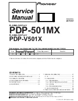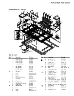
PDP-501MX, PDP-V501X
3
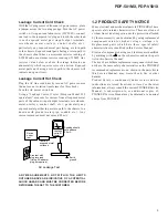
Leakage Current Hot Check
Plug the AC line cord directly into an AC power source
(do not use an isolation transformer for this check).
Turn the AC power switch on.
Using a "Leakage Current Tester (Simpson Model 229
equivalent)", measure for current from all exposed metal
parts of the cabinet (input/output terminals, screwheads,
metal overlays, control shaft, etc.), particularly any
exposed metal part having a return path to the chassis, to a
known earth ground (water pipe, conduit, etc.). Any
current measured must not exceed 0.5mA.
Leakage
current
tester
Reading should
not be above
0.5mA
Device
under
test
Test all
exposed metal
surfaces
Also test with
plug reversed
(Using AC adapter
plug as required)
Earth
ground
AC Leakage Test
ANY MEASUREMENTS NOT WITHIN THE LIMITS
OUTLINED ABOVE ARE INDICATIVE OF A POTENTIAL
SHOCK HAZARD AND MUST BE CORRECTED BEFORE
RETURNING THE SET TO THE CUSTOMER.
1.2 PRODUCT SAFETY NOTICE
Many electrical and mechanical parts in PIONEER set have
special safety related characteristics. These are often not
evident from visual inspection nor the protection afforded
by them necessarily can be obtained by using replacement
components rated for higher voltage, wattage, etc.
Replacement parts which have these special safety
characteristics are identified in this Service Manual.
Electrical components having such features are identified
by marking with a
on the schematics and on the parts
list in this Service Manual.
The use of a substitute replacement component which dose
not have the same safety characteristics as the PIONEER
recommended replacement one, shown in the parts list in
this Service Manual, may create shock, fire or other
hazards.
Product Safety is continuously under review and new
instructions are issued from time to time. For the latest
information, always consult the current PIONEER Service
Manual. A subscription to, or additional copies of,
PIONEER Service Manual may be obtained at a nominal
charge from PIONEER.
Leakage Current Cold Check
With the AC plug removed from an AC power source, place
a jumper across the two plug prongs. Turn the AC power
switch on. Using an insulation tester (DC 500V), connect
one lead to the jumpered AC plug and touch the other lead
to each exposed metal part (input/output terminals,
screwheads, metal overlays, control shafts, etc.),
particularly any exposed metal part having a return path
to the chassis. Exposed metal parts having a return path to
the chassis should have a minimum resistor reading of
0.3M
Ω
and a maximum resistor reading of 5M
Ω
. Any
resistor value below or above this range indicates an
abnormality which requires corrective action. Exposed
metal parts not having a return path to the chassis will
indicate an open circuit.
Summary of Contents for PDP-501MX
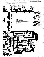
Page 16: ...PDP 501MX PDP V501X 16 A B C D 1 2 3 4 1 2 3 4 3 3 POWER SUPPLY MODULE 1 2 J 1 2 ...
Page 17: ...PDP 501MX PDP V501X 17 A B C D 5 6 7 8 5 6 7 8 J 1 2 ...
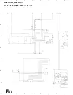
Page 18: ...PDP 501MX PDP V501X 18 A B C D 1 2 3 4 1 2 3 4 3 4 POWER SUPPLY MODULE 2 2 J 2 2 ...
Page 19: ...PDP 501MX PDP V501X 19 A B C D 5 6 7 8 5 6 7 8 J 2 2 ...

