PDP-501MX, PDP-V501X
81
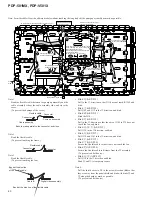
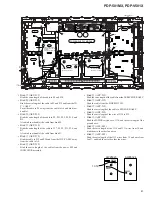
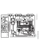
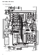
Always ensure a distance of
more than 35mm from the
board edge.
(To prevent sub field noise.)
Pull so that is does not
ride onto the sub frame.
Pull so that is does not
ride onto the sub frame.
From INDICATOR ASSY
H2
H9
H1
H3
H7
H11
H10
H8
H12
I
3
I
9
P7
P14
P11
P5
P8
W5
W7
P17
P19
P6
P12
A5
A6
P20
P1
A4
E13
P18
P25
P24
P23
P22
P21
P4
P2
P3
W1
A1
A2
A7
G8
W2
W17
W16
C2
C1
A3
P10
I
6
I
2
I
4
H4
I
5
H5
I
8
Y DRIVE B
CONTROL
Y DRIVE A
X DRIVE A
X DRIVE B
R G B
ANALOG VIDEO
POWER SUPPLY MODULE
F8
G7
F7
G6
F6
G5
F12
F17
F18
F19
F20
F10
F9
BIND
K
BIND
Z
BIND
O
BIND
J
BIND
D
BIND
U
BIND
L
BIND
V
BIND
X
BIND
M
PASSLOCK
S
BIND
N
BIND
A
BIND
C
BIND
B
J110
J110
35mm
FAN18
FAN13
FAN15
FAN20
FAN7
FAN8
FAN9
FAN12
FAN16
FAN14
FAN11
FAN10
FAN19
FAN5
FAN3
FAN4
FAN2
J112
Fan
C
SENSOR B ASSY
J112
J108
G15
G16
G17
G18
F1
CG3
CG5
CG2
CG1
CG4
CG6
From IR RECEIVER ASSY
From
SIDE SWITCH
From
POWER SWITCH
3D Y/C
B3
B2
B4
Note
• Bind
O
(AEP-215)
Bind the extra length of the cable to P6 and P10.
• Bind
M
(AEP-215)
Bind the extra length of the cable to P3 and P19 and from the 3D
Y/C ASSY.
Form the cable to P6 away from the cable to A4 and bind (not
bundle).
• Bind
N
(AEP-215)
Bind the extra length of the cable to P2, P21, P22, P4, P18, and
B5.
Also bind (not bundle) the cable from bind M.
• Bind
K
(AEP-215)
Bind the extra length of the cable to P17, P8, P5, P11, P14, and
B7.
Also bind (not bundle) the cable from bind N.
• Bind
J
(AEP-215)
Bind the cable to P12 and P20 and from the 3D Y/C ASSY away
from the cable to A4.
• Bind
D
(AEP-215)
Bind the extra length of the cables from the power SW and
INDICATOR assembly.
• Bind
B
(AEP-215)
Bind the extra length of the cable from the IR RECEIVER ASSY.
• Bind
X
(AEP-215)
Bind the cable from the SIDE SWITCH.
• Bind
Z
(AEP-215)
Bind the extra length of the cable to SENSOR B ASSY.
• Bind
U
(AEP-215)
Bind the extra length of the wire of J110 to P12.
• Bind
V
(AEP-215)
Bind the POWER switch wire, J110, and the extra length of the
ground wire.
• Bind
A
(AEC-093)
Bind the extra length of the J110 and J311 wires from 1F, and
bind them to the other fan wires.
• Bind
C
(AEC-093)
Bind the extra length of the J112 wires from 1F and wire from
fan
C
. and bind them to the other fan wires.
R8724
K8601
K8602
AWZ6323
13.5V
AWZ6324
Summary of Contents for PDP-501MX
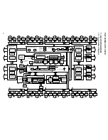
Page 16: ...PDP 501MX PDP V501X 16 A B C D 1 2 3 4 1 2 3 4 3 3 POWER SUPPLY MODULE 1 2 J 1 2 ...
Page 17: ...PDP 501MX PDP V501X 17 A B C D 5 6 7 8 5 6 7 8 J 1 2 ...
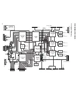
Page 18: ...PDP 501MX PDP V501X 18 A B C D 1 2 3 4 1 2 3 4 3 4 POWER SUPPLY MODULE 2 2 J 2 2 ...
Page 19: ...PDP 501MX PDP V501X 19 A B C D 5 6 7 8 5 6 7 8 J 2 2 ...


