Function description
Operating Manual PMCprotego S2-2(-C)
1002529-EN-04
17
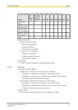
The table below shows which outputs signal the status of which safety function.
Output
In-
ternal
error
No safety
function
activated
SS1
SS2
SOS
SLS
SSR
SDI
SLI
STO Acknow-
ledge
x
x
x
x
x
x
x
x
x
SSA Safe Stand-
still Acknowledge
-
-
-
x
x
-
-
-
x
SDA Safe Direc-
tion Acknowledge
-
-
-
-
-
-
-
x
-
SRA Safe Range
Acknowledge
-
-
-
-
-
x
x
-
x
Ready
-
x
x
x
x
x
x
x
x
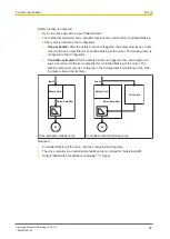
Signals at the output
}
"0"-signal (0 V) at the output:
–
Output is high impedance
–
No current to the load
–
Safety function not activated
}
"1"-signal (+24 V) at the output:
–
Output is low impedance
–
Current is supplied to the load
–
Safety function activated
Supply voltage
}
24 VDC connection to supply the safety card's digital outputs
4.2.2.2
Output test
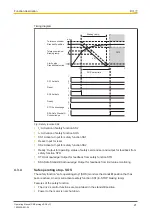
The outputs are tested regularly:
}
Outputs that are switched on are checked via regular off tests.
–
Test pulses for outputs that are switched on: see technical details
–
Outputs that are switched on are switched off for the duration of the test pulse.
–
The load must not switch off because of the test.
}
Outputs that are switched off are checked via regular on tests.
–
Test pulses for outputs that are switched off: see technical details
–
Outputs that are switched off are switched on for the duration of the test pulse.
–
The load must not switch on because of the test.
Testing for shorts
}
A test is regularly carried out to check for shorts between the outputs.


