- 5 -
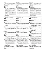
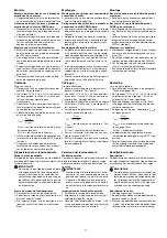
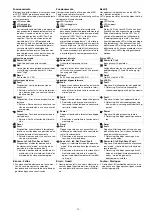
Betrieb
Das Gerät ist betriebsbereit, wenn die LED Po-
wer permanent leuchtet.
LEDs zeigen den Status und Fehler während
des Betriebs an:
LED leuchtet
LED blinkt
INFO
Statusanzeigen und Fehleranzeigen kön-
nen unabhängig voneinander auftreten. Bei
einer Fehleranzeige leuchtet oder blinkt die
LED "Fault" (Ausnahme: "Versorgungs-
spannung zu gering"). Eine zusätzlich blin-
kende LED weist auf eine mögliche
Fehlerursache hin. Eine zusätzlich statisch
leuchtende LED weist auf einen normalen
Betriebszustand hin. Es können mehrere
Statusanzeigen und Fehleranzeigen gleich-
zeitig auftreten.
Operation
The unit is ready for operation when the Power
LED is permanently lit.
LEDs indicate the status and errors during op-
eration:
LED on
LED flashes
INFORMATION
Status indicators and error indicators may
occur independently. In the case of an error
display, the "Fault" LED will light or flash
(exception: "Supply voltage too low"). An
LED that is also flashing indicates the po-
tential cause of the error. An LED that is lit
and is static indicates a normal operating
status. Several status indicators and error
indicators may occur simultaneously.
Exploitation
L'appareil est prêt à fonctionner lorsque la LED
Power reste allumée en permanence.
Les LEDs indiquent l'état et les erreurs lors du
fonctionnement:
LED allumée
LED clignotante
INFORMATION
L'affichage de l'état et des erreurs peut sur-
venir indépendamment. Lors de l'affichage
d'une erreur, la LED "Fault" s'allume ou cli-
gnote (exception : "Tension d'alimentation
trop faible"). Une LED clignotante supplé-
mentaire informe sur une cause possible
d'erreur. Une LED supplémentaire qui s'al-
lume de façon permanente informe de l'état
normal de fonctionnement. Plusieurs affi-
chages de l'état et des erreurs peuvent sur-
venir en même temps.
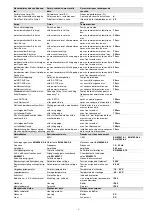
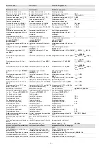
Statusanzeigen
Status indicators
Affichages d'état
Power, In1, In2
Eingangskreis ist geschlossen.
Power, In1, In2
Input circuit is closed.
Power, In1, In2
Le circuit d'entrée est fermé.
Out
Sicherheitskontakte sind geschlossen und
Halbleiterausgang Y32 führt High-Signal.
Out
Safety contacts are closed and semicon-
ductor output Y32 carries a high signal.
Out
Les contacts de sécurité sont fermés et la
sortie statique Y32 délivre un niveau haut.
Reset
An S34 liegt 24 V DC an.
Reset
24 VDC is present at S34.
Réarmement
24 V DC sur S34.
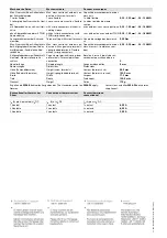
Fehleranzeigen
Error indicators
Affichage des erreurs
Fault
Diagnose: Abschlussstecker nicht gesteckt
`
Abhilfe: Abschlussstecker stecken, Ver-
sorgungsspannung aus- und wieder ein-
schalten.
Fault
Diagnostics: Plug terminator not connected
`
Remedy: Insert plug terminator, switch
supply voltage off and then on again.
Fault
Diagnostic : fiche de terminaison non bran-
chée
`
Remède : brancher la fiche de terminai-
son, couper puis remettre en marche la
tension d'alimentation
Fault
Diagnose: Interner Fehler, Gerät defekt
`
Abhilfe: Versorgungsspannung aus- und
wieder einschalten, gegebenenfalls Ge-
rät tauschen.
Fault
Diagnostics: Internal error, unit defective
`
Remedy: Switch supply voltage off and
then on again, change unit if necessary.
Fault
Diagnostic : erreur interne, appareil défec-
tueux
`
Remède : couper puis remettre en mar-
che la tension d'alimentation, si besoin
échanger l'appareil
Power
Diagnose: Versorgungsspannung zu gering
`
Abhilfe: Versorgungsspannung überprü-
fen.
Power
Diagnostics: Supply voltage too low
`
Remedy: Check the supply voltage.
Power
Diagnostic : tension d'alimentation trop fai-
ble
`
Remède : vérifier la tension d'alimenta-
tion
Reset
Fault
Diagnose: Unerlaubte Stellung eines Dreh-
schalters oder ein Drehschalter wurde wäh-
rend des Betriebs verstellt.
`
Abhilfe: Versorgungsspannung aus- und
wieder einschalten.
Reset
Fault
Diagnostics: Position of rotary switch is not
permitted or rotary switch was adjusted
during operation.
`
Remedy: Switch supply voltage off and
then on again.
Réarmement
Fault
Diagnostic : sélecteur rotatif dans une posi-
tion incorrecte ou un sélecteur rotatif à été
déréglé durant le fonctionnement.
`
Remède : couper puis remettre en mar-
che la tension d'alimentation.
Power, In1, In2, Out, Reset, Fault
Diagnose: Der Betriebsartenwahlschalter
"mode" steht in Grundstellung (senkrechte
Position)
`
Abhilfe: Versorgungsspannung aus-
schalten und am Betriebsartenwahl-
schalter "mode" gewünschte Betriebsart
einstellen.
Power, In1, In2, Out, Reset, Fault
Diagnostics: The operating mode selector
switch "mode" is in its start position (verti-
cal position)
`
Remedy: Switch off the supply voltage
and set the required operating mode on
operating mode selector switch "mode".
Power, In1, In2, Out, Reset, Fault
Diagnostic : le sélecteur de mode de mar-
che « mode » est positionné sur la position
de base (position verticale)
`
Remède : coupez la tension d'alimenta-
tion et régler le mode de fonctionnement
souhaité sur le sélecteur de mode de
marche « mode ».
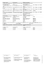
Fehler - Störungen
`
Fehlfunktionen der Kontakte: Bei ver-
schweißten Kontakten ist nach Öffnen des
Eingangskreises keine neue Aktivierung
möglich.
Faults - malfunctions
`
Contact malfunctions: If the contacts have
welded, reactivation will not be possible after
the input circuit has opened.
Erreurs - défaillances
`
Défaut de fonctionnement des contacts de
sortie : si les contacts sont soudés, un réar-
mement est impossible après ouverture du
circuit d'entrée.


