


PCM-072/phyCORE-AM64xx System on Module
L-860e.A0
© PHYTEC America L.L.C. 2022
58
7.2.3 Ethernet Reference Circuits
Example reference circuits for connecting the CPSW_RGMII1 differential signals from the on-board PHY to an RJ45
connector and PRG0_RGMII1 signals to an Ethernet PHY are shown below.
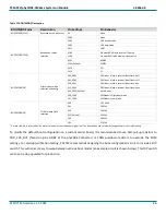
Figure 22. RJ45 Reference Schematic
The circuit consists of:
•
An Ethernet Jack
•
Two TVS diode arrays for ESD protection
•
Two voltage networks to manage the Ethernet LEDs in the jack