


PCM-072/phyCORE-AM64xx System on Module
L-860e.A0
© PHYTEC America L.L.C. 2022
28
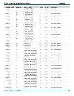
X1, Column B
Pin
Signal Name
Type
Level
Processor Ball
Description
B47
X_SPI0_D1
I/O
3.3V
J5
A14
SPI Data 1
B48
X_SPI0_D0
I/O
3.3V
J5
A13
SPI Data 0
B49
X_SPI0_CS1
I/O
3.3V
J5
C13
SPI Chip Select 1
B50
GND
-
-
-
Ground
B51
X_I2C0_SDA
I/O
3.3V
J5
B18
I2C0 Data
(2.2K pullup)
B52
X_I2C0_SCL
I/O
3.3V
J5
A18
I2C0 Clock
(2.2K pullup)
B53
X_MCU_UART0_RX
I/O
3.3V
J2
A9
UART Receive Data
B54
X_MCU_UART0_TX
I/O
3.3V
J2
A8
UART Transmit Data
B55
GND
-
-
-
Ground
B56
X_MCU_UART0_RTS
I/O
3.3V
J2
E8
UART Request to Send (active low)
B57
X_MCU_UART0_CTS
I/O
3.3V
J2
D8
UART Clear to Send (active low)
B58
X_PRG1_PRU0_GPO5
I/O
3.3V
J4
V13
PRU Data Output
B59
X_PRG1_PRU1_GPO8
I/O
3.3V
J4
U12
PRU Data Output
B60
GND
-
-
-
Ground
B61
X_PRG0_PRU0_GPO19
I/O
3.3V
J4
W1
PRU Data Output
B62
X_PRG0_PRU0_GPO18
I/O
3.3V
J4
V1
PRU Data Output
B63
X_PRG0_PRU0_GPO5
I/O
3.3V
J4
R3
PRU Data Output
B64
X_PRG0_PRU0_GPO8
I/O
3.3V
J4
T2
PRU Data Output
B65
GND
-
-
-
Ground
B66
X_PRG0_PRU0_GPO17
I/O
3.3V
J4
U1
PRU Data Output
B67
X_PRG0_PRU0_GPO7
I/O
3.3V
J4
T1
PRU Data Output
B68
X_PRG0_MDIO0_MDC
I/O
3.3V
J4
P3
PRU MDIO Clock
B69
X_PRG0_MDIO0_MDIO
I/O
3.3V
J4
P2
PRU MDIO Data
B70
GND
-
-
-
Ground
J2:
The voltage level for this signal is configurable for 1.8V or 3.3V via J2. The default voltage level is listed here, but always check the actual jumper setting for the
applicable SOM configuration. Refer to section
for details
J4:
The voltage level for this signal is configurable for 1.8V or 3.3V via J4. The default voltage level is listed here, but always check the actual jumper setting for the
applicable SOM configuration. Refer to section
for details
J5:
The voltage level for this signal is configurable for 1.8V or 3.3V via J5. The default voltage level is listed here, but always check the actual jumper setting for the
applicable SOM configuration. Refer to section
for details
1:
More information about this signal can be found in section
Table 9 phyCORE-AM64xx Connector X1, Column C Pinout
X1, Column C
Pin
Signal
Type
Level
Processor Ball
Description
C1
X_GPMC0_AD3/BOOTMODE_3
1
I/O
3.3V
J6
U20
GPMC Data 3 Input/Output
(100K pullup/pulldown network)
C2
X_GPMC0_AD4/BOOTMODE_4
1
I/O
3.3V
J6
U18
GPMC Data 4 Input/Output
1
(100K pullup/pulldown network)
C3
X_GPMC0_AD5/BOOTMODE_5
1
I/O
3.3V
J6
U19
GPMC Data 5 Input/Output
(100K pullup/pulldown network)
C4
X_GPMC0_AD6/BOOTMODE_6
1
I/O
3.3V
J6
V20
GPMC Data 6 Input/Output
(100K pullup/pulldown network)
C5
GND
-
-
-
Ground
C6
X_GPMC0_AD7/BOOTMODE_7
1
I/O
3.3V
J6
V21
GPMC Data 7 Input/Output
(100K pullup/pulldown network)
C7
X_GPMC0_AD8/BOOTMODE_8
1
I/O
3.3V
J6
V19
GPMC Data 8 Input/Output
(100K pullup/pulldown network)
C8
X_GPMC0_AD9/BOOTMODE_9
1
I/O
3.3V
J6
T17
GPMC Data 9 Input/Output
(100K pullup/pulldown network)


