


PCM-072/phyCORE-AM64xx System on Module
L-860e.A0
© PHYTEC America L.L.C. 2022
32
J2
:
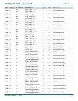
The voltage level for this signal is configurable for 1.8V or 3.3V via J2. The default voltage level is listed here, but always check the actual jumper setting for the
applicable SOM configuration. Refer to section
for details
J4
:
The voltage level for this signal is configurable for 1.8V or 3.3V via J4. The default voltage level is listed here, but always check the actual jumper setting for the
applicable SOM configuration. Refer to section
for details
J5
:
The voltage level for this signal is configurable for 1.8V or 3.3V via J5. The default voltage level is listed here, but always check the actual jumper setting for the
applicable SOM configuration. Refer to section
for details
J6
:
The voltage level for this signal is configurable for 1.8V or 3.3V via J6. The default voltage level is listed here, but always check the actual jumper setting for the
applicable SOM configuration. Refer to section
for details
1:
This signal should not be driven during reset. More information can be found in section
2:
Do not use this signal if the on-board ethernet PHY is populated
4.10 Thermal Management
Thermal management is necessary to ensure proper operation of the phyCORE-AM64xx SOM, especially when integrated
inside of an enclosure as the AM64xx processor generates considerable heat.
The phyCORE-AM64xx has a temperature rating of -40C to 85C. PHYTEC has found that a fan and a heatsink help prevent
overheating at the higher end of the phyCORE-AM64xx’s temperature operating range (during our temperature testing a
BDN09-6CB/A01 heatsink was attached to the SOM). The following parts are used to attach the fan to the phyCORE-
AM64xx SOM processor and to connect the fan power cable to the connector on the PHYTEC phyCORE-AM64xx Carrier
Board:
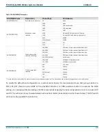
Table 11 Thermal Management Parts
Recommended Thermal Component
Part Number
Heatsink
BDN10-3CB/A01
5VDC Fan
MF25100V1-1000U-A99
Fan Connector
DF13-4S-1.25C
2x Fan Crimping Terminals
DF13-2630SCF
Carrier Board Connector
DF13-4P-1.25V(75)
3x #4 5/8’’ Screws
90190A112
The heatsink is mounted on top of the processor with heatsink adhesive. Then the crimping terminals are crimped to the
exposed fan wires, which allows the fan to be mounted to the 5-pin connector that mates with the PHYTEC Carrier board.
Finally, the fan is secured to the heatsink with screws. The PHYTEC Carrier Board supplies 5V power to the fan via the
DF13-4P-1.25V(75) connector. The fan circuit on the AM64xx Carrier Board is shown below and allows for user control
over the fan.


