


PCM-072/phyCORE-AM64xx System on Module
L-860e.A0
© PHYTEC America L.L.C. 2022
48
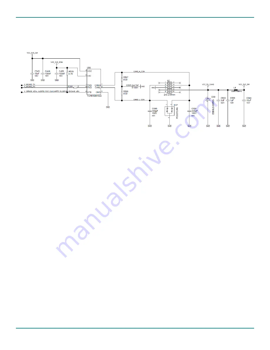
7.1.2 CAN Reference Circuit
An example reference circuit for connecting the MCAN0 signals to a 2X5 connector is shown below.
Figure 21. MCAN0 Reference Schematic
The circuit consists of:
•
A 2x5 header
•
A CAN FD Transceiver to convert the MCAN0 signals into differential CAN bus signal levels
7.2 Ethernet
The phyCORE-AM64xx SOM brings out five external 10/100/1000 Mbps Ethernet ports (the AM64xx processor has six
internal ethernet ports, but two share the same pins and can’t be used simultaneously, CPSW_RGMII2 and PRG1_RGMII2):
•
One is translated on the SOM by a DP83867IRRGZ Ethernet PHY (a robust, low power transceiver) into the
differential Ethernet data pairs that are accessible at the phyCORE-Connector. This Ethernet PHY:
o
Supports 10-BASE-Te, 100BASE-TX, and 1000BASE-T protocols to interface directly to twisted pair media
through an external transformer.
o
Provides two LED control outputs and one GPIO signal. The GPIO and LED I/O also serve as bootstrap pins for
PHY configuration. Be careful to avoid pulling or driving these signals during power up and reset.
•
The other four are brought out as RGMII/RMII/MII
o
CPSW_RGMII1 and CPSW_RGMII2 can be used as either RGMII or RMII
o
PRG0_RGMII1, PRG0_RGMII2, PRG1_RGMII1, and PRG1_RGMII2 can be used as either RGMII or MII
The on-board Ethernet PHY offers several default configuration options that include settings such as the PHY address and
RGMII clock skew. Options such as these can be set via external strapping resistors which are described in the datasheet.
The table below lists the default Ethernet PHY strapping configuration; however, these settings can be changed via the


