


3 Product Specification
3.3.1
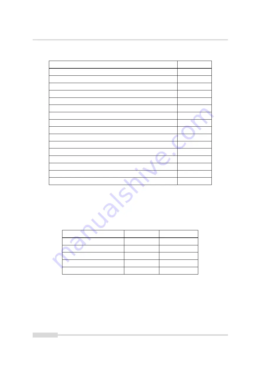
Absolute Maximum Ratings
Parameter
Value
Power Supply Voltage
-50 V ... +50 V
ESD Contact Discharge Power Supply
4 kV
ESD Air Discharge Power Supply
8 kV
Fast Transients/Bursts Power Supply
2 kV
Surge immunity Power Supply
1 kV
Camera Control Input Signal Voltage Single Ended
-15 V ... +30 V
Camera Control Input Signal Voltage RS422
-15 V ... +40 V
Camera Control Input Signal Voltage HTL
-15 V ... +40 V
Common Mode Range Voltage RS422
-15 V ... +20 V
Camera Control Output Signal Voltage Single Ended
0 V ... +30 V
Camera Control Output Signal Output Current Single Ended
0.5 A
Camera Control Output Signal Output Power Single Ended
0.5 W
ESD Contact Discharge Camera Control Signals
10 kV
ESD Air Discharge Camera Control Signals
7 kV
Fast Transients/Bursts Data and Camera Control Signals
1 kV
Surge immunity Data and Camera Control Signals
1 kV
Table 3.5: Absolute Maximum Ratings
3.3.2
Electrical Characteristics
In the following tables, VIN is the input voltage for single ended input and VID is the input
voltage for differential input.
Single Ended Input Voltage
Logic Level
Fault Condition
-15V < VIN < +0.8V
Low
No Fault
+0.8V < VIN < +2.0V
Indeterminate
No Fault
+2.0V < VIN < +15V
High
No Fault
+15V < VIN < +18V
High
Indeterminate
+18V < VIN < +40V
High
High Input Fault
Table 3.6: Single-Ended TTL Mode Receiver Logic (LineIn0, LineIn1, LineIn2 & LineIn3)
.
22 of 151
MAN085 04/2021 V1.3
Summary of Contents for Luxima DR4-D1280-L01-FB
Page 8: ...CONTENTS 8 of 151 MAN085 04 2021 V1 3...
Page 12: ...1 Preface 12 of 151 MAN085 04 2021 V1 3...
Page 42: ...4 Image Acquisition 42 of 151 MAN085 04 2021 V1 3...
Page 52: ...5 Counter Timer 52 of 151 MAN085 04 2021 V1 3...
Page 84: ...12 Pixel Data Processing 84 of 151 MAN085 04 2021 V1 3...
Page 94: ...12 Pixel Data Processing 94 of 151 MAN085 04 2021 V1 3...
Page 98: ...13 Precautions 98 of 151 MAN085 04 2021 V1 3...
Page 128: ...16 Troubleshooting 128 of 151 MAN085 04 2021 V1 3...
Page 134: ...19 Support and Repair 134 of 151 MAN085 04 2021 V1 3...
Page 136: ...20 References 136 of 151 MAN085 04 2021 V1 3...
Page 140: ...A Pinouts 140 of 151 MAN085 04 2021 V1 3...