


14
IS16
English
1.4
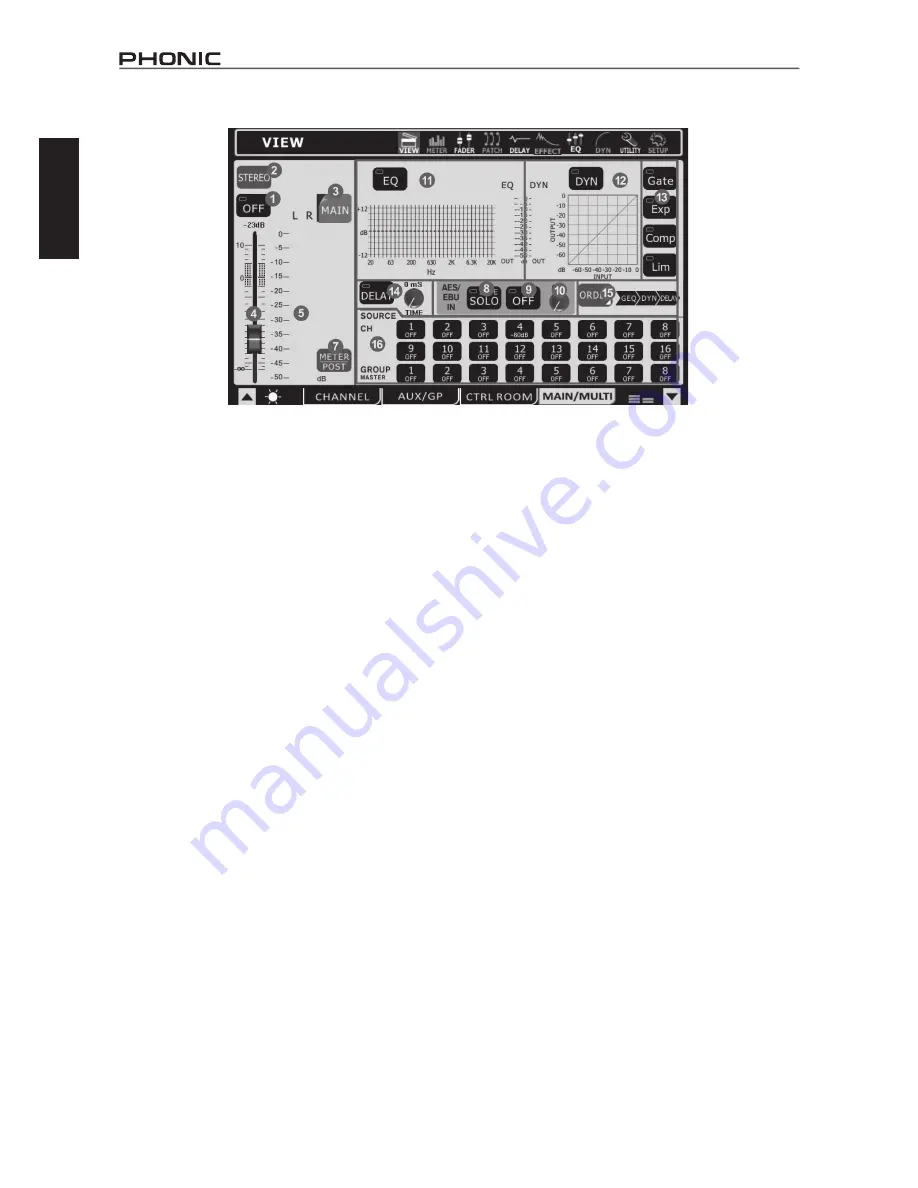
Main / Multi Tab
1.4.1
On / Off Button
This button will turn the currently selected output channel on
and off.
1.4.2
Main Mono/Stereo Select
Using this option users are able to select whether the Main mix is
a stereo or mono mix. When mono is selected, the left and right
channels will be combined as a mono channel.
1.4.3
Channel Select
Using this button – and the resulting pop-up menu – users are
able to select from any of the Multi Output channels as well as
the Main stereo mix. Once selected, the channel’s properties will
then appear on screen.
1.4.4 Fader
This fader determines the final output level of the currently selected
output channel.
1.4.5
Level Meter
This level meter displays the final output level of the appropriate
Multi or Main output. When monitoring the Main mix, a stereo level
meter will be displayed.
1.4.6
EFX Assign Buttons
Push either of these buttons to assign the output from the
corresponding Effect processor to the main or multi output. The
EFX1 and EFX2 buttons will only appear in the corresponding
view page when the corresponding multi output or the main mix
is selected as the source signal for one or both of the Effect
processors.
1.4.7
Meter Pre/Post Button
Pushing this button will allow users to adjust the level meter
between a pre-fader meter and a post-fader meter.
1.4.8
AES/EBU In SOLO Button
This will activate the solo function on the AES/EBU Input signal.
When the AES/EBU input is set to SOLO SAFE, the word SAFE
will appear within this button.
1.4.9
AES/EBU On Button
When the Main mix is selected, the AES/EBU button will allow
the Digital input signal (received through the AES/EBU input) to
be sent to the main mix. The Digital output signal (sent from the
AES/EBU output), taken from the main stereo mix out, will always
be activated.
1.4.10
AES/EBU Trim
This parameter enables you to trim the level of the AES/EBU input
signal in the digital domain.
1.4.11
EQ On / Off and Display
The EQ button will turn the equalizer of the currently selected
output channel on and off. The graph that accompanies it will
display the current EQ properties of that channel. A level meter
can be found beside the graph. Clicking on / selecting the graph
will allow users to jump directly to the EQ function screen.
1.4.12
Dynamic Processor On / Off and Display
Pushing this button turns the dynamic processor on and off. The
display that accompanies it gives a quick visual representation of
the dynamic processes currently set. A level meter can be found
to the left of the dynamic processor graph. To jump to the dynamic
processor function, simply click the graph onscreen.
1.4.13
Dynamic Processor
The buttons situated to the right turn the individual dynamic
processes on and off. There is a single button for each the Gate,
Expander, Compressor and Limiter. When a process is activated
(ie. the threshold is passed) the corresponding button will light
up yellow.
1.4.14
Delay Function
The delay button allows users to activate and deactivate a delay
on the currently selected output. Users are also able to adjust
the possible delay time from 1 millisecond to 1 second. Adding
a delay to output channels can help to compensate for distance
between speakers in large multi-speaker setups. A delay time of
one millisecond per foot (or 3 milliseconds per meter) that the
speaker is away from the stage is the general rule of thumb in
this application.
1.4.15
Processing Order Selection
Users are able to select in which order the currently selected
output channel will pass through the EQ and Dynamic Processor
functions.
1.4.16
Source Assign Buttons
T
hese buttons allow users to immediately assign any of the listed
channels to the currently selected mix. The buttons will also show
the output level for the corresponding mix (expressed in decibels).
When the Main mix is selected, any of the input channels and
the Group mixes can be assigned. When viewing the channel
properties of any of the Multi outputs, users are able to select the
source from any of the Group or AUX mixes.
A Note on Group Sources and Panning
It is important to note that the IS16 has an Intelligent Group
Panning System (IGPS) programmed into its DSP. When channel
sources for the group signal are panned set dead center, the Group
signal will simply be a mono signal. In the event one or more of
your Group sources (from the channels) is panned left or right, the
IS16’s IGPS will divide these for Group mixes. Signals panned left
on channels will be sent to odd-numbered Groups (1, 3, 5 or 7)
when selected as a destination, while selecting even numbered
Groups (2, 4, 6 or 8) will allow these to receive signals that are
panned to the right. When sending Group mixes to the Main mix,
panning is automatically set dead-center and can be adjusted to
the left and right as necessary. However Group mixes that are
assigned to Multi outputs are once again restricted to the left-odd,
right-even rule mentioned above. Group mixes panned left can
only be sent out through odd-numbered Multi outputs, while those
panned right are sent out even-numbered outputs (as assigned).
Summary of Contents for IS16v1
Page 1: ...User s Manual IS16v1 Manual del Usuario...
Page 50: ...Espa ol...
Page 98: ......
Page 99: ......
Page 100: ......


