Circuit Descriptions, List of Abbreviations, and IC Data Sheets
EN 93
F21RE AB
9.
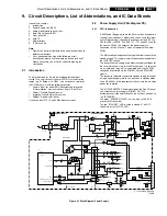
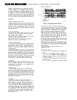
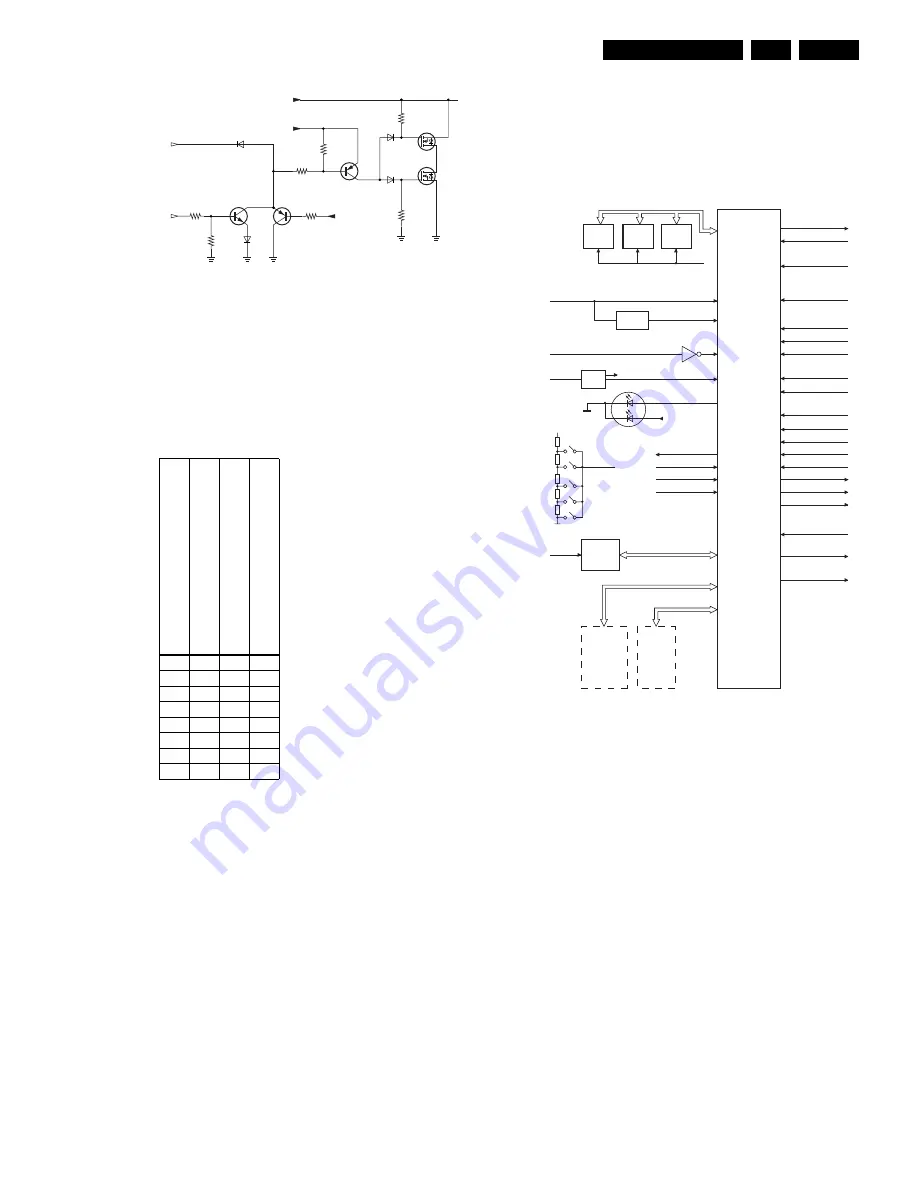
Figure 9-7 Audio mute circuitry
The table below shows how this is done. It is controlled by the
following signals:
•
POWER_VALID line is a control signal generated by the
power supply.
•
SOUND_ENABLE line is a control signal coming from the
microprocessor on the SSP.
•
+5VSTBY line, from the Front panel.
Table 9-2 Truth table audio mute
When the SOUND_ENABLE signal is high, the two N-channel
FETs are conducting the audio signal to the GND, and will mute
the audio output.
Why are two FETs implemented? Because in a case of "no
mute", and FET 7868 directly connected to ground, the diode
in this FET would distort the audio signal too much. With the
addition of FET 7867, this distortion is eliminated, because this
FET is connected in anti-series.
The supply for the inverter is connected to the +5VSTBY. This
supply signal is always available when the Mains is connected,
so in case the Mains voltage is disconnected, the mute function
is disabled.
9.4
Small Signal Panel (SSP, diagram K)
The SSP is based on the one used in the MG3.1 chassis. It
consists of the following parts:
1.
Control.
2.
Video: Tuner and IF.
3.
Video: HIP.
4.
Video: Feature Box.
5.
Video: HOP.
6.
Audio
9.4.1
SSP: Control
The control part can be divided into:
•
Set Control
•
TXT/OSD
•
Remote Control
Set Control
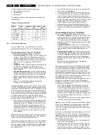
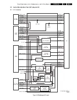
Figure 9-8 Block diagram Control part (
µ
P)
The SAA5801 (IC7003) is called the OTC (OSD, TXT, and
Control). In this IC, the microprocessor and the TXT-decoder
(or Closed Caption for the USA) are integrated. The SAA5801
is also called the OTC2.5 because also TXT-level 2.5 is
supported.
At start up, the RESET signal is generated with TS7006/7007.
During a reset, all I/O pins are high. When a RESET is
generated, the set is in Standby mode.
The 8V6 and the 5V2 are sensed by pins 105 and 106. If one
of them is not present, the Power supply is switched "off". The
OTC will generate an error code to indicate what was wrong.
The horizontal (HOSD-PIP) and vertical (VD) pulses are also
fed to the OTC for stable OSD and CC. To create good stable
pulses, these signals are inverted and fed to the OTC. The
RGB-outputs (77/78/79) together with fading (pin 80) are fed to
the HOP. This fading pin has a double function:
•
Make the menu transparent.
•
Fast-blanking for CC.
There are three I2C busses used (see section "I2C overview"):
1.
Slow I2C bus (max. 100 kHz) for tuner, DW, video-, and
audio selection.
2.
Fast I2C bus (max. 400 kHz) for the HIP, MSP, TOPIC,
HOP, and FBX (PICNIC, and FALCONIC).
3.
NVM I2C bus for the Non Volatile Memory to avoid data
corruption.
POWER_VALID (fr
o
m PSU)
SOUND
_ENABLE (from uP
on SSP)
+5
VSTB
Y
(
fr
om
Fr
on
t Pa
n
e
l)
SIGNAL
MUT
E
D
0
0
0
1
0
0
1
1
0
1
0
1
0
1
1
1
1
0
0
1
1
0
1
0
1
1
0
1
1
1
1
1
7835
7862
6835
3836
150K
3865
7865
7868
47K
6862
POWER_VALID
SOUND_ENABLE
CL16532098_006.eps
180901
3867
100K
6867
6868
10K
3835
3861
10K
3862
10K
+5VSTBY
+5VSTBY
3868
100K
AUDIO-SIGNAL (LEFT)
7867
CL 36532021_005.eps
180303
SAA580X
P50-OUT
SEL_IN_2
STATUS SC3
FRONT DETECT
120
A0...A19
D0...D15
CVBS-TXT-DW-OUT
7001
5
7
KEYBOARD
107
90
+5V
106
+8V6
UART-OUT
105
91/92
+3V3
113
+5VSTBY
RESET
RED
GREEN
STBY-LED
74
H, V
83,84
119
117
109
LIGHT SENSOR
110
IR-LED
114
108
SEL_IN_1
103
STANDBY
104
POWER-VALID
99
CONFIG-IDENT
98
RC5/RC6
100
P50-IN
97
SDM
96
SOUND ENABLE
95
RESET AUDIO
94
ENA-SCALER
93
UART-IN
89
RGB, BLENDING
77,78,79,80
FRAME
81
FLASH
(EPG)
FLASH
(SW)
DRAM
(TXT)
EEPROM
M24C32
NVM
TUNER
FDS
3D COMB
I/O SELECT V
I/O SELECT A
AVI
HIP
HOP
FBX
MSP
SAM
+3V3 +
RESET
PEAKING
FILTER
+3V3
8V6
+3V3
I2C3
+3V3
I2C2
I2C1
85/86
87/88
slow
fast
Summary of Contents for F21RE
Page 7: ...Directions for Use EN 7 F21RE AB 3 3 Directions for Use ...
Page 8: ...Directions for Use EN 8 F21RE AB 3 ...
Page 9: ...Directions for Use EN 9 F21RE AB 3 ...
Page 10: ...Directions for Use EN 10 F21RE AB 3 ...
Page 11: ...Directions for Use EN 11 F21RE AB 3 ...
Page 12: ...Directions for Use EN 12 F21RE AB 3 ...
Page 13: ...Directions for Use EN 13 F21RE AB 3 ...
Page 14: ...Directions for Use EN 14 F21RE AB 3 ...
Page 15: ...Directions for Use EN 15 F21RE AB 3 ...
Page 16: ...Directions for Use EN 16 F21RE AB 3 ...
Page 17: ...Directions for Use EN 17 F21RE AB 3 ...
Page 18: ...Directions for Use EN 18 F21RE AB 3 ...
Page 19: ...Directions for Use EN 19 F21RE AB 3 ...
Page 20: ...Directions for Use EN 20 F21RE AB 3 ...
Page 21: ...Directions for Use EN 21 F21RE AB 3 ...
Page 22: ...Directions for Use EN 22 F21RE AB 3 ...
Page 23: ...Directions for Use EN 23 F21RE AB 3 ...
Page 24: ...Directions for Use EN 24 F21RE AB 3 ...
Page 25: ......
Page 114: ...Revision List EN 114 F21RE AB 11 11 Revision List First release ...

