Service Modes, Error Codes, and Fault Finding
EN 35
F21RE AB
5.
5.5.3
Error Codes
If the set has non-intermittent faults, clear the error buffer
before you begin the repair. This to ensure that old error codes
are no longer present.
If possible, check the entire contents of the error buffer. In
some situations, an error code is only the result of another error
code and not the actual cause of the problem (for example, a
fault in the protection detection circuitry can lead to a
protection).
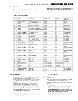
Table 5-3 Error Code Overview
5.6
Protections
The microprocessor (OTC) of the F21R Receiver box remains
active during standby. This because power of the
microprocessor (and the attached memory chip set) is coming
from the 3V3 supply, which is derived from the 5V Standby
circuitry.
Therefore, in both "Power on" as in "Standby" mode, the
microprocessor is connected to this power supply. The
microprocessor controls the "Standby" line for switching "on"
and "off" the main supply. In the standby mode, or in the
protection mode, the "Standby" line will open the contacts of
relay 1400 (diagram PS) via T7401, which results in switching
"off" the mains input to the main supply.
We can divide the chassis protections in two groups:
1.
I2C protections: from I2C-busses (fast and slow) or I2C-IC
errors (device errors).
2.
OTC input protections.
5.6.1
I2C Protections
During normal operation, some registers of the I2C controlled
ICs are refreshed every 200 milliseconds. During this
sequence, the three I2C busses and the I2C ICs will also be
checked.
Possible protections:
•
I2C bus protections. This will take place if the SDA and
SCL are short-circuited to ground or to each other.
•
I2C device protections. This can occur when there is a
malfunction in the communication with one specific device,
or if the power supply of the device is missing.
•
FBX and/or Tuner circuitry protection. If one of these
circuits does not respond for more than 1 second
Error
Device
Description
Defective item
Diagram
Defective module
indication
2
ST24E32 or M24C32
Non volatile memory
IC7008
K7
Control
3
SAA580x
OTC2.5 microprocessor/TXT
IC7003
K7
Control
5
UV1316
Tuner
U1102
K1
Tuner
10
TEA6415
I/O source select video
IC7208
K8
Source select
11
TEA6422
I/O source select audio
IC7777
K8
Source select
15
TDA9320
HIP I/O-video processing
IC7501
K1
Chroma IF IO
20
TDA9330
HOP video control/deflection proc-
essor
IC7300
K6
Video Controller
21
TDA9178 (if present)
LTP Peaking (TOPIC)
IC7402
K6
Video Controller
23
UPD64083 (if present)
3D Comb IC
IC7023
C0
3D Comb Filter
25
MSP34xxx
ITT sound processor
IC7751
K3
Audio Module
27
PCF8574
I/O Expander
IC7880
AV8
AV-Interface
30
TEA6415
Video Selection Switch
IC7710
AV7
AV-Interface
31
TEA6422
Audio Selection Switch
IC7810
AV8
AV-Interface
33
ACEX-EPLD
HD signal/sync processing
IC7360
AV3
AV Interface
35
UV1316 (if present)
FDS Tuner
U1102
M1
Video Dual Screen
Panel
36
PCF8574 (if present)
FDS I/O Expander
IC7860
M2
Video Dual Screen
Panel
37
SAB9079 (if present)
FDS Popov
IC7700
M4
Video Dual Screen
Panel
38
TDA9320 (if present)
FDS HIP2
IC7501
M1
Video Dual Screen
Panel
39
M24C04 (if present)
FDS NVM
IC7991
M1
Video Dual Screen
Panel
41
TDA7309 (if present)
FDS Headphone
IC7620
M5
Video Dual Screen
Panel
50
SAA4978
FBX Picnic
IC7611
L1
Feature Box
52
T8F24EF (if present)
FBX Eagle
IC7724
L2
Feature Box
53
SAA4992
FBX Falconic
IC7626
L3
Feature Box
65
Slow I2C bus blocked
See block diagram
Slow I2C Blocked
66
Fast I2C bus blocked
See block diagram
Fast I2C Blocked
67
Supply 5V
5V2
See block diagram
+5V Supply
68
Supply 8V
8V6
See block diagram
+8V Supply
77
Featurebox protection
FBX prot.
+3V FBX Supply
80
Tuner protection
Tuner prot.
U1102
K1
+8V Tuner Supply
81
UPD64083 (if present)
3D Comb prot.
IC7023
C0
3D Comb Filter
Summary of Contents for F21RE
Page 7: ...Directions for Use EN 7 F21RE AB 3 3 Directions for Use ...
Page 8: ...Directions for Use EN 8 F21RE AB 3 ...
Page 9: ...Directions for Use EN 9 F21RE AB 3 ...
Page 10: ...Directions for Use EN 10 F21RE AB 3 ...
Page 11: ...Directions for Use EN 11 F21RE AB 3 ...
Page 12: ...Directions for Use EN 12 F21RE AB 3 ...
Page 13: ...Directions for Use EN 13 F21RE AB 3 ...
Page 14: ...Directions for Use EN 14 F21RE AB 3 ...
Page 15: ...Directions for Use EN 15 F21RE AB 3 ...
Page 16: ...Directions for Use EN 16 F21RE AB 3 ...
Page 17: ...Directions for Use EN 17 F21RE AB 3 ...
Page 18: ...Directions for Use EN 18 F21RE AB 3 ...
Page 19: ...Directions for Use EN 19 F21RE AB 3 ...
Page 20: ...Directions for Use EN 20 F21RE AB 3 ...
Page 21: ...Directions for Use EN 21 F21RE AB 3 ...
Page 22: ...Directions for Use EN 22 F21RE AB 3 ...
Page 23: ...Directions for Use EN 23 F21RE AB 3 ...
Page 24: ...Directions for Use EN 24 F21RE AB 3 ...
Page 25: ......
Page 114: ...Revision List EN 114 F21RE AB 11 11 Revision List First release ...

