Circuit Descriptions, List of Abbreviations, and IC Data Sheets
EN 88
F21RE AB
9.
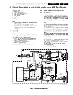
The Power Supply module consists of three parts:
1.
Mains voltage inlet and filter.
2.
Standby supply.
3.
Main supply.
The total power balance of the supply can be read from the
following table:
Table 9-1 Total power balance
9.2.2
PSU: Start-up Sequence
For a description of the "start-up sequence", we make a
differentiation between the FTV1.9 and the FM2x monitors.
Start-up sequence for an E-box + FTV1.9 Monitor
There are five different "power states" in the E-box:
•
Low Power Standby (P < 0.9 W). The Main supply is not
working. Only the OTC and I/O Expanders (on the AVI-
panel) are powered from the 5VSTB. The OTC works in
one of the low power states (no program execution, but the
UART, timer, RC pre-processor, and SW ADC are
working).
•
Standby (P < 3 W). The Main supply is not working. Only
the OTC and I/O Expanders (on the AVI-panel) are
powered from the 5VSTB. The OTC works in high power
state (= normal).
•
Semi Standby (Europe only). The Main supply is working.
All PWBs are powered. The video in the HOP and the audio
on the AVI board are muted. The sync is not send to the
monitor. This state is used for EPG and P50 operations.
•
On (P < 35 W). The Main supply is working. All PWBs are
powered.
•
Off. The OTC and I/O Expanders are not powered
anymore. All the voltages are "off".
The E-box will always start-up in the "Standby" state until the
CONFIG_IDENT is detected (means monitor attached). During
initialisation, the E-box must check the "TV_standby" bit in the
NVM, to decide into which state the E-box and monitor have to
be put. This will set the STANDBY pin on the OTC accordingly.
The initialisation starts when the E-box is switched "on" and the
AC-power is connected. As a result, the 5VSTB supply is
activated, and the OTC is activated. Now, the OTC checks the
presence of the CONFIG_IDENT signal:
•
If this check is successful (this means two following "hand
shake" sequences are detected), then the state of the E-
box depends on the "TV_standby" bit in the NVM. This bit
contains the history data about how previously the TV
configuration entered the "standby" state (e.g. when this
was done by the user (bit= 1), the set will stay in "standby").
•
If this check is not successful, the E-box will go to "Low
Power Standby".
Note: For service, the E-box can work in "Stand-alone" power
mode. This is detected via the "Stand alone" bit in the NVM.
This bit can be set in the Dealer/Service menu.
If the E-box is switched from "Standby" to "On", the STANDBY
pin of the OTC is pulled "low", the relay switch is closed, and
the main supply is started up. When the 5V2 and 8V6 voltages
reach their nominal values, the 5V2_PROT and 8V6_PROT
are activated. Now:
1.
The MSP shall be reset first, as this IC can disturb the I2C
traffic, when not reset properly.
2.
Secondly, as the POPOV IC of the DW (F2R22 only) can
pull the slow SDA line "low" when the HA signal from the
main HIP is not available, all traffic on the slow I2C bus
needs to be delayed until the HIP is properly initialised and
settled. This means a wait state of 100 ms, after the crystal
configuration of the HIP has correctly been read out.
3.
Next, all other ICs are initialised. Now, the E-box is
working, but the monitor is still not displaying a picture.
4.
The HOP switches on the PHI1 loop, the software sets all
the necessary video and audio parameters, and enables
them.
Start-up sequence for an E-box + FM2x Monitor
There are five different "power states" in the E-box:
•
Low Power Standby (P < 0.9 W). The Main supply is not
working. Only the OTC, I/O Expanders (on the AVI-panel)
and remote circuits are powered from the 5VSTB. The
OTC works in one of the low power states (no program
execution, but the UART, timer, RC pre-processor, and SW
ADC are working).
•
Peripheral Standby (P < 3 W). This is an intermediate
state. This mode is only used temporarily, if the OTC goes
from low power standby to normal operation and vice
versa.
•
Semi Standby (Europe only). The Main supply is working.
All PWBs are powered. The video in the HOP and the audio
on the AVI board are muted. The sync is not send to the
monitor. This state is used for EPG and P50 operations.
•
On (P < 35 W). The Main supply is working. All PWBs are
powered.
•
Off. The OTC and I/O Expanders are not powered
anymore. All the voltages are "off".
The E-box will always start-up in the "Standby" state until the
AYT (Are You There) is detected. This means that an FM2x
monitor is attached (this is different from the FTV1.9 monitor,
where a separate CONFIG_IDENT line is used). During
initialisation, the E-box must check the "Stand_alone" bit in the
NVM. If this bit and the "TV_standby" bit both are not set, the
AYT protocol is started, and will wake up the monitor. This will
set the STANDBY pin on the OTC accordingly.
The initialisation starts when the E-box is switched "on" and the
AC-power is connected. As a result, the 5VSTB supply is
activated, and the OTC is activated. Now, the OTC checks the
presence of the "Standby" bit:
•
If the "Standby" bit and the "Stand_alone" (or "Service/
Factory") bit are not set, the AYT protocol is enabled,
which will wake up the monitor. If this check is successful,
the state of the E-box depends on the "TV_standby" bit in
the NVM. This bit contains the history data about how
previously the TV configuration entered the "standby" state
(e.g. when this was done by the user (bit= 1), the set will
stay in "standby").
•
If this check is not successful (e.g. set to standby by user),
the E-box will go to "Low Power Standby".
Note: For service, the E-box can work in "Stand-alone" power
mode. This is detected via the "Stand alone" bit in the NVM.
This bit can be set in the Dealer/Service menu. If this bit is
"high", the AYT protocol is not used and no FSP commands are
send to the monitor.
If the E-box is switched from "Low Power Standby" to "On", the
STANDBY pin of the OTC is pulled "low", the relay switch is
closed, and the main supply is started up. When the 5V2 and
8V6 voltages reach their nominal values, the 5V2_PROT and
8V6_PROT are activated. Now:
1.
The MSP shall be reset first, as this IC can disturb the I2C
traffic, when not reset properly.
2.
Secondly, as the POPOV IC of the DW (F22Rx only) can
pull the slow SDA line "low" when the HA signal from the
main HIP is not available, all traffic on the slow I2C bus
needs to be delayed until the HIP is properly initialised and
Supply
Value
(V)
Tolerance
(%)
Typ. Current
(A)
P_max
(W)
5V2
5.2
3
2.0
13
8V6
8.6
7
1.25
13.8
+7.7V_audio
8.6
7
0.1
1.2
-7.7V_audio
-5.2
7
0.1
1.2
33V_tuner
33
4 mA max.
0.1
5VSTB
5.32
5
0.3
2.7
Summary of Contents for F21RE
Page 7: ...Directions for Use EN 7 F21RE AB 3 3 Directions for Use ...
Page 8: ...Directions for Use EN 8 F21RE AB 3 ...
Page 9: ...Directions for Use EN 9 F21RE AB 3 ...
Page 10: ...Directions for Use EN 10 F21RE AB 3 ...
Page 11: ...Directions for Use EN 11 F21RE AB 3 ...
Page 12: ...Directions for Use EN 12 F21RE AB 3 ...
Page 13: ...Directions for Use EN 13 F21RE AB 3 ...
Page 14: ...Directions for Use EN 14 F21RE AB 3 ...
Page 15: ...Directions for Use EN 15 F21RE AB 3 ...
Page 16: ...Directions for Use EN 16 F21RE AB 3 ...
Page 17: ...Directions for Use EN 17 F21RE AB 3 ...
Page 18: ...Directions for Use EN 18 F21RE AB 3 ...
Page 19: ...Directions for Use EN 19 F21RE AB 3 ...
Page 20: ...Directions for Use EN 20 F21RE AB 3 ...
Page 21: ...Directions for Use EN 21 F21RE AB 3 ...
Page 22: ...Directions for Use EN 22 F21RE AB 3 ...
Page 23: ...Directions for Use EN 23 F21RE AB 3 ...
Page 24: ...Directions for Use EN 24 F21RE AB 3 ...
Page 25: ......
Page 114: ...Revision List EN 114 F21RE AB 11 11 Revision List First release ...

