Pfaff 3568-12/22 Instruction Manual Download Page 28

Mounting and commissioning the machine

9 - 1

9

Mounting and commissioning the machine

After unpacking the machine, check it for any transport damage. In case of damage, inform

the shipping company and the responsible PFAFF dealer.

The machine must only be mounted and commissioned by qualified personnel!

All relevant safety regulations are to be observed!

9

.01

Mounting

Suitable connections for supplying electricity and compressed air must be available at the

machine’s location (refer to 

chapter 3 Specifications

).

The location where the machine is set up must have a flat, sturdy surface.

Lift the machine with a forklift from the shipping pallet.

Screw the six enclosed rubber springs onto the legs.

Set down the machine on the ground and make sure it is standing horizontally by pushing

the legs.

Attach stacker frame and align.

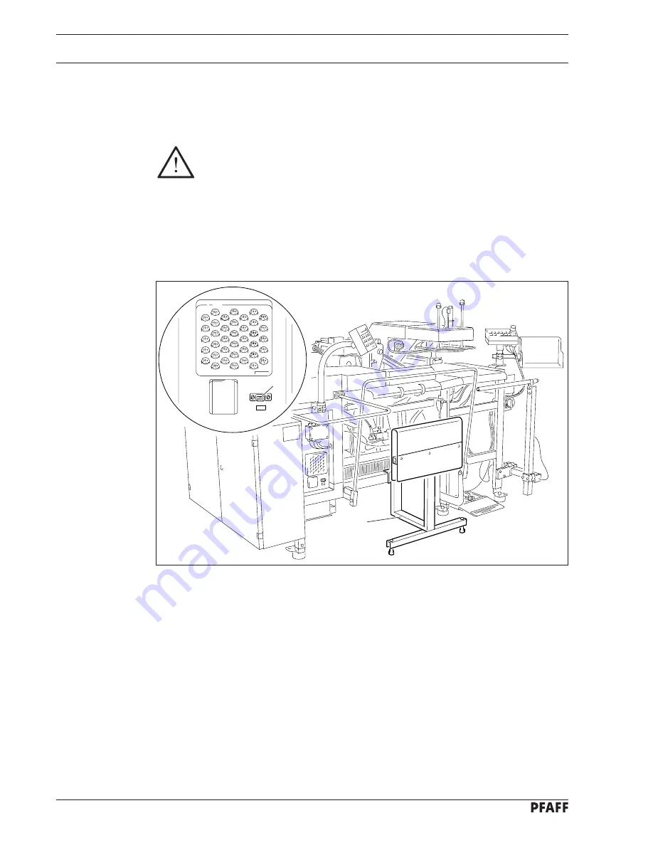
Plug disk drive into socket 

2

.

Fig. 9 - 01

1

2

Summary of Contents for 3568-12/22

Page 1: ...3568 12 22 Instruction manual 296 12 17973 Betriebsanleitungengl 03 97...

Page 2: ...copying or translation of PFAFF Instruction Manuals whether in whole or in part is only permitted with our previous authorization and with written reference to the source G M PFAFF Aktiengesellschaft...

Page 3: ...e customer s premises 6 1 6 02 Transport within the customer s premises 6 1 6 03 Disposal of the packaging 6 1 6 04 Storage 6 1 7 Explanation of the symbols 7 1 8 Controls 8 1 8 01 On off switch 8 1 8...

Page 4: ...08 Placement of the cuttings 10 11 11 Programing and sewing 11 1 11 01 Brief description of Input mode 11 1 11 01 01 Direct functions 11 1 11 01 02 Summary of the functions in the 1st menu level 11 1...

Page 5: ...needle in the needle hole in the direction of sewing 13 5 13 06 03 Needle bar parallel guide 13 6 13 06 04 Setting zero stitch 13 7 13 06 05 Zigzag stitch movement 13 8 13 06 06 Needle penetration sy...

Page 6: ...ing the sewing jig 13 46 13 08 06 Sewing jig position at the folding station home position 13 47 13 08 07 Proximity switch 13 48 13 08 08 Height of the loading plate 13 49 13 08 09 Height of pocket pl...

Page 7: ...ated and all valid environmental protection regulations Applicable local regulations of the social insurance society for occupational accidents or other supervisory organizations are to be strictly ad...

Page 8: ...ted to the power supply Exceptions to this are contained in the regulations EN 50110 Modifications and alterations to the machine must only be carried out pursuant to all relevant safety regulations O...

Page 9: ...rsons operate and work on the machine Further information can be obtained at the point of sale 1 05 Operating and specialist personnel 1 05 01 Operating personnel Operating personnel are persons respo...

Page 10: ...e Instruction Manual switch off the On Off switch before carrying out adjustments or repairs and ensure that it cannot be switched on again unintentionally never work on parts and devices which are st...

Page 11: ...fore operating the machine make sure that safety switch 1 in the control box is switched on Do not operate the machine under any circumstances if the safety switch 1 has been turned off Danger of inju...

Page 12: ...ions Any and all uses of this machine which have not been approved of by the manufacturer are considered to be inappropriate The manufacturer cannot be held liable for any damage caused by the inappro...

Page 13: ...Nm Sewing motor AEG Permanent Magnet AC Servo Motor Motor speed max 4500 rpm 1 Connection voltage 230 V 50 60 Hz AC Power requirement approx 1000 VA Working air pressure min 6 bar Air consumption appr...

Page 14: ...um brass and various plastics The electrical equipment consists of plastics and copper The machine must be disposed of in accordance with applicable local environmental protection regulations Special...

Page 15: ...ine was tested according to EN 60204 3 1 version 1 86 The following tests were carried out on the machine proper connection of the protective conductor systems a visual check b testing connection of p...

Page 16: ...ustomer s premises or to the location of use 6 03 Disposal of the packaging The packaging of these machines consists of paper cardboard and VCE fibre The proper disposal of the packaging is the respon...

Page 17: ...bols In this Instruction Manual tasks to be carried out and important information are drawn to your attention by symbols The symbols have the following meanings Note information Cleaning care Lubricat...

Page 18: ...to the machine is switched on or off Fig 8 01 8 1 8 02 EMERGENCY OFF switch By pressing the EMERGENCY OFF switch 1 the machine can be stopped in case of an emergency Before the machine is turned back...

Page 19: ...rol 1 is activated the sewing jig and the transport arm jig changeover are disconnected 8 04 Table control When control 1 is activated the retaining flap for the cuttings is raised so that the workpie...

Page 20: ...on HOME POSITION POCKET PLATE IN FRONT on PLAIN FABRIC off HOME POSITION POCKET PLATE IN FRONT off PLAIN FABRIC off HOME POSITION POCKET PLATE IN FRONT off PLAIN FABRIC on Move forward pocket plate 1...

Page 21: ...ced Fig 8 06 1 1 Menu combinations Start control functions HOME POSITION POCKET PLATE IN FRONT on PLAIN FABRIC on Move forward folder Lower pocket plate and move forward folder Move forward folder Low...

Page 22: ...he corresponding symbol Program number 0 99 Jig code option Stitch length in mm Maximum speed in min 1 Actual speed in min 1 Counter Various texts e g input prompt error message etc appear in the bott...

Page 23: ...dual operation modes only certain functions can be used depending on the mode 8 07 03 Program station keys These keys activate functions in all three operation modes AUTOMATIC MANUAL and INPUT Via the...

Page 24: ...automatically Seam pattern backwards Sew seam pattern backwards step by step Combined with the program start key the seam pattern sequence is carried out automatically Home position Bring X Y carriag...

Page 25: ...eys or the plus minus keys The value entered must be confirmed with the Enter key Reset stitch counter For resetting the bobbin thread stitch counter following an unplanned bobbin change Enter key For...

Page 26: ...0 8 2 0 7 4 8 08 01 Operation mode keys The keys have the same function as those on the control panel of the sewing station refer to chapter 8 07 02 Operation mode keys Operation mode AUTOMATIC Operat...

Page 27: ...er movement Carries out folder functions step by step Single steps of the machine without sewing Only in MANUAL operation mode Home position Brings folder and transport arm into starting position Prog...

Page 28: ...are to be observed 9 01 Mounting Suitable connections for supplying electricity and compressed air must be available at the machine s location refer to chapter 3 Specifications The location where the...

Page 29: ...ed air must always be supplied with lubricated air Clean the machine thoroughly checking the electrical cables and pneumatic connecting hoses for any damage Oil machine and or fill with oil see chapte...

Page 30: ...4 by pulling up on it Turn master switch 5 to ON Press the On key on the control panel of the folder The machine is now in the INPUT operation mode When the machine is commissioned the zero point mus...

Page 31: ...achine Select INPUT mode Display CHOOSE FUNCTION OR SCROLL 250 Via the plus minus key select the 2nd menu and confirm with Enter Display 2 MENU 261 In the 2nd menu press number key 6 to select the SER...

Page 32: ...lay SERVICE 800 Select MANUAL mode to bring the X Y control to home position Press transport arm sewing jig to swing the transport arm to the sewing station Press home position key twice Insert adjust...

Page 33: ...witch in the control box is turned on 10 01 Inserting the needle Fig 10 01 Lift ratchet lever 1 and swing in safety bar 2 until it is resting against the machine Press seam pattern forwards key Press...

Page 34: ...02 and wind it clockwise around bobbin 1 a few times Switch on the bobbin winder while at the same time pressing bobbin winder spindle 2 and cam 3 The bobbin fills up while you are sewing If the bobb...

Page 35: ...remove bobbin case 4 Inserting bobbin in bobbin case Insert the bobbin so that the bobbin turns in the direction of the arrow when the thread is pulled Thread according to Fig 10 04 and regulate the t...

Page 36: ...me position press the change bobbin key Transport arm with sewing jig is swung over to the folder station and the sewing head is tilted up Raise ratchet lever 1 and swing safety bar 2 until it rests a...

Page 37: ...d swing safety bar 2 until it rests against the machine Carry out bobbin change see 10 03 01 Bobbin change bobbin case and bobbin thread tension Return safety bar 2 to its starting position Press rese...

Page 38: ...folder station Thread the needle thread according to Fig 10 07 Adjust the thread pre tension at nut 4 Regulate the thread main tension at nut 5 In the sewing index Press transport arm sewing jig key t...

Page 39: ...he program selection key Enter the number of the desired program with the number keys End the input with the operation mode keys AUTOMATIC or MANUAL If the program selected is not in the machine memor...

Page 40: ...ram must be stored in each of both program stations see chapter 10 05 Program number selection Select the INPUT mode Display CHOOSE FUNCTION OR SCROLL 250 Press automatic station change key End the in...

Page 41: ...y 2 MENU 261 Call up the 2nd menu level by pressing Enter Display 2 MENU 300 Press number key 4 Display SWITCH FUNCTIONS 560 Press number key 4 again Display OTHER FUNCTIONS 660 Press number key 3 Dis...

Page 42: ...1 Bit assignment Ones place Bit 3 Bit 2 Bit 1 Bit 0 Tens place Bit 7 Bit 6 Bit 5 Bit 4 0 free free free free 1 free free free magnet 2 free free magnet free 3 free free magnet magnet 4 free magnet fr...

Page 43: ...ch Menu combination HOME POSITION POCKET PLATE IN FRONT ON PLAIN FABRIC ON Slide the pocket cutting onto the pocket plate according to Fig 10 11 Menu combination HOME POSITION POCKET PLATE IN FRONT ON...

Page 44: ...E IN FRONT ON PLAIN FABRIC OFF Activate the foot switch pocket plate moves forward Slide the pocket cutting onto the pocket plate according toFig 10 11 Activate the foot switch pocket plate is lowered...

Page 45: ...Direct functions are functions which are required more often than other functions They can be selected directly via the corresponding keys Program station A Program station B Program selection Automa...

Page 46: ...OUTPUTS 7 COLD START 5 SET ZERO POINT 2 READ ALL PROGRAMS FROM DISK 1 DELETE ONE PROGRAM MEMORY 2 DELETE ALL PROGRAMS MEMORY 3 DELETE ONE PROGRAM DISK 3 BOBBIN SENSOR 1 GERMAN 2 ENGLISH 3 FRENCH 4 SP...

Page 47: ...tions with the plus minus keys until you find the display Display 2 MENU 261 Call the 2nd menu level by pressing Enter basic position 2nd menu Display 2 MENU 300 11 02 03 2nd menu level After entering...

Page 48: ...STITCH GENERATION RUNNING 264 The new stitch length value is assumed Display CHOOSE FUNCTION OR SCROLL 250 11 03 02 Selecting a function from the 1st menu level To activate the PLAIN MATERIAL functio...

Page 49: ...4 Display SWITCH FUNCTIONS 560 Press number key 4 again Display OTHER FUNCTIONS 660 Press number key 2 Display BOBBIN CHANGE FROM TOP OFF ON 1 673 Press number key 1 Display BOBBIN CHANGE FROM TOP ON...

Page 50: ...keys or the number keys 3 TIME FOR FEED ROLLER When this function is selected the running time of the feed rollers for stacking is displayed in seconds The running time can be changed via the plus mi...

Page 51: ...r output of the commands for DELAY ZIGZAG ON and OFF must be delayed as a function of the speed 8 INTERMEDIATE STOP When this function is selected the display shows whether the function is on or off I...

Page 52: ...rolling function 2 READ PROGRAM FROM DISK From this subfunction further subfunctions can be called 1 READ ONE PROGRAM FROM DISK 2 READ ALL PROGRAMS FROM DISK Depending on the selected subfunction all...

Page 53: ...he user can program counters according to his requirements in the subfunctions The values are always changed using the plus minus keys or the number keys 1 REM STITCH COUNT NDL THR MON The number of s...

Page 54: ...ances the value should be between60 and120 4 SWITCH FUNCTIONS Under this main function the user can program machine functions according to his requirements in the subfunctions 1 THREAD MONITOR FUNCTIO...

Page 55: ...ses the amount of thread when starting sewing 2 BOBBIN CHANGE FROM TOP Sewing head tilts up automatically for changing the bobbin 3 JIG MONITOR option 4 LABEL FEEDER option The label is fed automatica...

Page 56: ...ntil the table is at the top 5 TIME FOR EDGE FOLDERS The time is to be set so that the folder moves to the top after the folder plate is at the back end position 6 TIME FOR FEED FORWARD The time is to...

Page 57: ...ing the program cycle do not reach into the folder or the sewing station area Danger of serious injury During the program cycle do not reach into the swivel range of the transport arm Danger of seriou...

Page 58: ...8 06 Start controls Start the cycle of functions of the folder by pressing the folder movement key repeatedly Lower folder and table Engage folder slide raise table retract folder slide Raise folder S...

Page 59: ...AD ERROR 008 The machine moves back automatically by the number of stitches selected in the menu and stops Thread the needle see chapter 10 04 Threading the needle thread If necessary press the seam p...

Page 60: ...hangeover every 6 months Clean the blower air filter as required Check air pressure daily before use Clean air filter of the compressed air unit as required Clean the vaporizer jet of the compressed a...

Page 61: ...compartment and the needle area of the sewing head several times daily Clean the entire machine at least once a week To do this Select MANUAL operation mode With the machine in home position press th...

Page 62: ...hose 1 into oil reservoir 2 Before the machine is first operated or whenever the machine has been at a standstill for a longer period of time also add a few drops of oil to the hook race The oil flow...

Page 63: ...nd a density of 0 865 g cm3 at 15 C When required Raise ratchet lever and swing in safety bar toward the machine as far as it will go Unscrew screw 2 Pour in oil until it is level with the uppermost m...

Page 64: ...vy duty grease with a penetration of 265 295 and a dripping point of 185 C Open X Y control cover Lubricate both guides via the grease nipples 1 and 2 with a grease gun This should be done every 6 mon...

Page 65: ...on the control panel of the folder station Transport arm with sewing jig swings to home position Press key 1 for the sewing jig changeover Changeover of transport arm and sewing jig frame is released...

Page 66: ...filter in the control box Before opening the control box be sure to turn off the main switch and ensure that it cannot be switched back on accidentally Open control box Press inward on the catches 2 a...

Page 67: ...so that the manometer 1 indicates a pressure of approx 6 bar 12 07 02 Cleaning the air filter The air filter must be cleaned whenever the working pressure of 6 bar is no longer achieved Turn off compr...

Page 68: ...If required unscrew container 2 and clean e g with benzine Screw container 2 back on Observe the seal Open screw 3 and fill oil into the container until the oil level is 10 15 mm below the top of cont...

Page 69: ...e oil vaporizer This adjustment is not required when the machine is not operated with lubricated air Adjust regulating screw 5 so that adequate lubrication of the cylinders and valves is guaranteed 1...

Page 70: ...gauges and other accessories 1 set of screwdrivers with blade widths from 2 to 10 mm 1 set of wrenches with jaw widths from 6 to 22 mm 1 set of Allan keys from 1 5 to 6 mm 1 universal screwdriver wit...

Page 71: ...rod 5 on transport arm Position frame 6 horizontally and connect support 7 Remove split pin 8 and push down lever 9 Remove sewing machine head For work beneath the bedplate raise support 10 and tilt b...

Page 72: ......

Page 73: ......

Page 74: ...pin in the appropriate hole and apply pressure Rotate the handwheel back and forth slightly until the adjustment pin engages in the crank slot behind the bearing plate thus blocking the machine Hole 1...

Page 75: ...chine head 13 06 01 Counterweight Requirement In needle bar position BDC the largest eccentricity of the counterweight 1 must be at the top 2 1 Fig 13 03 13 4 Move needle bar to BDC Turn counterweight...

Page 76: ...Unscrew counter presser and needle guard Insert a new needle Loosen screws 1 and remove thread trimmer unit Swing bobbin opener 2 screw 3 to the right and remove hook Fit hook bearing adjustment gaug...

Page 77: ...the greatest eccentricity of pin 4 toward the bottom Move the recess of the guide bar 5 against the eccentric pin 4 Turn eccentric pin 4 according to the requirement and tighten nut 3 Push guide rod...

Page 78: ...heel is turned 1 2 Place a piece of paper over the needle plate cutout and by turning the handwheel perforate with the needle Turn handwheel backwards until the paper is perforated again Both perforat...

Page 79: ...he needle bar must not move when the zigzag stitch width regulator is operated Loosen screws 1 slightly Bring needle bar to TDC hole 2 Move eccentric 2 until the distance from it to the right inner si...

Page 80: ...needle penetration 13 9 Fully retract the plunger of the cylinder 1 Place a piece of paper under the needle and perforate it Turn so that the needle moves up somewhat and extend the plunger of cylind...

Page 81: ...ection of sewing Requirement In straight stitch position viewed across the direction of sewing the needle must be centered exactly in the needle hole in the hook bearing adjustment gauge 1 2 Fig 13 09...

Page 82: ...idth the needle must not strike against the counter presser 13 11 1 2 Fig 13 10 Loosen the lock nut of pin 1 Slide pin 1 according to the requirement into the elongated hole of the lever 2 By moving t...

Page 83: ...ment gauge 4 at the top and from the side 13 12 418 419 438 439 4 3 Loosen screw 3 and loosen the draw key under the screw head by tapping the screw head lightly Move and or turn the hook bearing 5 ac...

Page 84: ...a fine line of oil after approx 10 seconds on a paper strip held over the needle plate cutout The adjustment is only required when the wick is replaced After replacing the wick make sure that the new...

Page 85: ...ned so that the machine does not bind and the gears do not have any play 2 3 4 1 Fig 13 13 Move eccentric bearing bush 1 screw 2 so that the drive belt 3 is positioned in the middle of the bobbin case...

Page 86: ...ght Requirement At needle bar position TDC hole 2 the distance between the needle point and the needle plate must be approx 19 mm Fig 13 14 1 2 3 4 5 1 2 3 4 5 19 mm 1 Move needle bar screws 1 without...

Page 87: ...e the distance between the needle and the hook point must be from 0 05 to0 1mm 2 The bobbin case position stop is to be mounted so that between the bobbin case base and the front edge of the bobbin ca...

Page 88: ...t When in the left hand zigzag position the hook point is at the center of the needle the upper edge of the needle eye must be 0 5 mm below the hook point 1 2 3 4 5 0 5 mm 1 Move needle bar screws 1 w...

Page 89: ...bin case opener the bobbin case position stop must be positioned at the center of the slot in the bobbin case base 5 1 3 2 0 6 mm Loosen screw 1 Place the bobbin case opener 2 against the right side o...

Page 90: ...movement Requirement With the needle bar 2 4 mm past BDC hole 1 bobbin case opener 3 must be at its right point of reversal Fig 13 18 Adjust bobbin case opener eccentric 1 screws 2 in accordance with...

Page 91: ...g stroke Requirement At needle bar position BDC the counter presser is to have just reached the top of its stroke 1 3 3 2 Unscrew counter presser 1 Move needle bar to BDC Turn eccentric 2 screws 3 acc...

Page 92: ...the needle is 3 mm the needle guard finger 1 must be at its back point of reversal Unscrew needle guard 1 Turn crank 2 screw 3 according to requirement 1 Turn the handwheel in rotating direction until...

Page 93: ...back point of reversal be at a distance of 0 5 mm to the needle Adjust the height of the needle guard 1 by adjusting the needle guard bracket 2 screws 3 according to requirement 1 By turning the hand...

Page 94: ...rsal of the counter presser 1 its surface must be parallel to and 0 3 mm under the cover plate 6 13 23 5 3 0 3 mm 1 6 4 2 Fig 13 22 Bring counter presser 1 to its top point of reversal Turn lifting cr...

Page 95: ...6 1 mm and the needle when it penetrates is centered in the needle hole in the counter presser 3 Loosen screws 4 just enough so that the eccentric 5 is difficult to turn on the shaft Bring needle bar...

Page 96: ...ed the distance to the bedplate must be 17 mm Lower presser Move presser screw 1 according to requirement 1 Allow the presser to be raised Loosen screw 2 Place spacer with a height of 17 mm underneath...

Page 97: ...release olive 5 the distance between the tension disks must be at least 0 5 mm Loosen screws 1 2 and 3 Lift the presser and place spacer with a height of 17 mm underneath it Adjust the distance betwee...

Page 98: ...re positioned at the highest point of the release olive5 By turning the tension release shaft accessible via screwdriver through hollow shaft 4 adjust the distance between the tension disks according...

Page 99: ...Thread check spring Requirement The stroke of thread check spring 3 must be approx 5 mm 2 2 5 mm 3 Tilt sewing machine head upright and insert Turn tension block 1 screws 2 according to the requiremen...

Page 100: ...le seam start is ensured 2 1 3 Fig 13 27 Move cylinder carrier 1 screws 2 according to the requirement The timing of the thread puller must be set so that the cylinder of the thread puller can carry o...

Page 101: ...ent The bobbin winder must disengage when the thread level is approx 1 mm from the edge of the bobbin Move trip 1 screw 2 according to the requirement If the bobbin is wound unevenly adjust the thread...

Page 102: ...s to position at TDC of the needle bar hole 2 1 2 Fig 13 29 Allow sewing machine to carry out positioning switch on off Mark this position on the shaft see arrow Bring the needle bar to TDC hole 2 Tur...

Page 103: ...pins on the trimmer and control units and remove connecting rod 3 Unscrew control unit screws 4 To mount bring needle bar to 2 4 past BDC hole 1 Mount control unit and connect pull rod 2 Screw on con...

Page 104: ...must be flush with the right side of the latch 7 13 33 24V 4 ED 837 14 44 3 3 4 6 4 7 2 1 7 5 5 Fig 13 31 Remove catch spring 1 screws 2 together with the cover disk Loosen screws 3 and 4 Turn contro...

Page 105: ...of the roller lever 4 must be centered at the cam recess of the control cam 7 13 34 24V 4 ED 37 14 45 7 4 6 1 2 3 4 7 5 Loosen screws 1 and 2 Press the rock shaft 3 to the right Adjust the roller leve...

Page 106: ...f 0 3 mm between the latch 2 and the largest eccentricity of the trip of the control cam 1 By turning the handwheel position the trip of the control cam 1 with its largest eccentricity under the latch...

Page 107: ...0 3 mm between the engaging lever 1 and the latch 2 24V 4 ED 0 2 0 3 mm 1 2 3 4 Bring needle bar to 2 4 past BDC hole 1 Operate engaging lever 1 by hand until the latch 2 engages Press the magneto ind...

Page 108: ...ase of the control cam 3 Fig 13 35 4 2 1 3 4 5 1 0 2 mm Bring needle bar to 2 4 past BDC hole 1 Operate actuating lever 1 by hand Press roller lever 2 until it is at the base of the control cam 3 Posi...

Page 109: ...Requirement With the needle bar at TDC hole 2 and the thread trimmer in resting position there must be a distance of 0 3 to 0 5 mm between the roller of the roller lever 3 and the outside diameter of...

Page 110: ...mer screws 1 Make sure that the knife blade is in perfect condition Move the thread catcher 2 by hand over the knife 3 until the cutout in the thread catcher 2 can be seen Insert a thread twice in thi...

Page 111: ...flush with the edge of the mounting plate 4 4 3 1 2 61 mm Fig 13 38 Mount the thread trimmer in the bedplate and align so that the distance between the front edge of the thread trimmer and the back e...

Page 112: ...r is in resting position there must be a distance of 0 2 mm between the catch spring 4 and the roller lever 9 2 2 1 3 8 5 9 4 0 2 mm 7 6 mm 6 Bring needle bar to BDC Operate engaging lever Adjust the...

Page 113: ...e Y direction 2 is to be 15 mm on the carriage for the X direction 4 1 2 2 4 3 15 mm 18 mm Adjusting the switch vanes 1 and 3 is only necessary when the carriage guides have been replaced or when the...

Page 114: ...nd positions must be 100 mm 13 43 Fig 13 41 6 6 6 5 1 2 3 4 Turn stop 1 nut 2 according to the requirement Detach pull rod 3 Swing transport arm 4 to folding station Align carrier 5 screws 6 according...

Page 115: ...he table 3 When the jig changes over the jig frame must not move Fig 13 42 Move eccentric pin 1 nut 2 according ot the requirements 1 and 2 Repeat this work step until both adjustments are correct Ali...

Page 116: ...must be resting against the sewing changeover without pressure Turn stop screw 1 nut 2 according to requirement 1 Adjust rod 3 screw 4 according to requirement 2 The feed speed of the sewing jig as it...

Page 117: ...tern forwards until the sewing jig groove is under the needle Position the needle point in the sewing jig groove by turning the handwheel By repeatedly pressing the keys seam pattern forwards and or s...

Page 118: ...be parallel 25 mm Swing sewing jig 1 in front of the folding station Turn stop screw 2 nut 3 according to requirement 1 Turn eccentric pin 4 nut 5 according to requirement 2 Recheck left end position...

Page 119: ...d 6 to the proximity switches 1 and 3 must be 46 mm in each case Swing the sewing jig in front of the sewing station Move proximity switch 1 screw 2 according to requirement 1 Swing the sewing jig in...

Page 120: ...wered Underneath the table work loose the lock nut of the plunger from the cylinder 1 Open compressed air table raises By turning screws 2 lock nut 3 and the plunger of the cylinder 1 adjust the heigh...

Page 121: ...e flush with the raised table 4 Turn screws 1 grub screws 2 according to the requirement Depending on the size of the pocket plate the plungers which are not in the pocket plate area can be lowered To...

Page 122: ...sions of the folder The folders are mounted according to basic dimensions from the factory These dimensions may not be changed when adjustments are carried out Only make adjustments described in this...

Page 123: ...Requirement The folder table and the machine table must be at the same height Loosen nuts 1 and screws 2 Align folder device by turning eccentric pins 3 according to the requirement Tighten nuts 1 an...

Page 124: ...e moved with difficulty Align pocket plate arm by moving the bearing housing according to requirement 1 Turn off compressed air Remove pocket plate 3 and measure the distance to the edge of the table...

Page 125: ...position Requirement The pocket plate 1 must be centered and parallel to the table 2 a b b a 2 1 Align the pocket plate 1 nuts 2 so that measurements a are the same The same applies to measurements b...

Page 126: ...asily move a panel of fabric positioned under the pocket plate 3 When the pocket plate is lowered it must just touch the fabric positioned under it it must not apply pressure to the fabric however Tur...

Page 127: ...prox the thickness of the fabric under the underside of the pocket plate 3 The angular strips 8 must be positioned on all sides at the same distance of 0 3 to 1 mm depending on the fabric to the pocke...

Page 128: ...ht of die by turning the nut 5 lock nut 6 according to requirement 2 Align die 2 screws 1 nuts 7 so that its outer edges are flush with the pocket plate edges Align angular strips 8 according to requi...

Page 129: ...it Unscrew screw 1 and remove the entire folder unit Align folder plate 2 according to requirement 1 screws 3 Insert folder plate 2 and adjust distance to die 4 according to requirement 2 screws 5 Pos...

Page 130: ...d e c d position 3 Switching f f e f e position 4 Switching g g f g f position 5 Switching h g position 1 2 3 Fig 13 56 The actuating sequence and the number of folder plates and the number of switchi...

Page 131: ...with screw1 Adjust the entering delay of the third fourth and if available fifth switching position on the regulating valves 2 of the corresponding cylinders Adjust the exiting delay of the folder pl...

Page 132: ...lanted side of the folder plate and overlap by 1 to 2 mm 2 The corner folders must be positioned 1 to 2 mm under the folder plates depending on the fabric thickness Align the corner folders 1 accordin...

Page 133: ...rement The folder installation shown in Fig 13 58 is for the third pocket style For other pocket styles refer to the table found in chapter 13 08 16 Actuating sequence of the folder plates for the cyl...

Page 134: ...Adjustment 13 08 20 Parallelism of seam to pocket Requirement The seam must run parallel to the pocket edge Turn eccentric pin 1 nut 2 according to the requirement 13 63 Fig 13 59 1 2...

Page 135: ...djustment 13 08 21 Centering the pocket seam Requirement The seam must be the same distance at the right and left to the pocket edge Turn screw 1 nut 2 according to the requirement 13 64 Fig 13 60 2 1...

Page 136: ...Distance of seam to pocket Requirement The seam is to be at the same distance on all sides to the pocket edge Turn adjusting screw 1 toggle switch 2 and clamp lever 3 according to the requirement Fig...

Page 137: ...Seam backtack distance Requirement The distance between the seam backtack and the pocket opening is to be approx 1 mm Adjust stops 1 screws 2 on the pocket plate according to the requirement Fig 13 62...

Page 138: ...ding to Fig 13 63 When newly installing or making the folder plates make sure that they lie behind the corners of the pocket plate by at least the amount of the fabric thickness on the marked spots In...

Page 139: ...23 have been carried out 1 1 1 2 mm 1 2 mm 30 30 2 Fig 13 64 With the folder plates fully extended transfer the front edges of the pocket stops 1 and the outer edge of the pocket plate 2 to the latera...

Page 140: ......

Page 141: ......

Page 142: ...ostfach 3020 D 67653 Kaiserslautern K nigstr 154 D 67655 Kaiserslautern Telefon 0631 200 0 Telefax 0631 172 02 Telex 45753 PFAFF D Gedruckt in der BRD Printed in Germany Imprim en R F A Impreso en la...

Reviews: