background image


Petwalk Solutions GmbH & Co KG 

User Guide 

Page 86 of 88 

Petwalk Solutions GmbH & Co KG 

User Guide 

Page 86 of 88 

18.2


WARRANTY 

The user (customer) is granted a manufacturer's guarantee under the following conditions 
irrespective of any claim against a possibly involved retailer: 


New devices and their components, which have any kind of defect because of fabrication 
and/or material faults, are going to be repaired by Petwalk Solutions GmbH & Co KG at its 
own choice, or replaced, if repair is disproportionate. For wear parts (battery, seals, 
decorations, clutch), this warranty is limited to 6 months from time of purchase. 


This warranty does not apply if the defect is due to improper treatment of the device, to 
intervention by the purchaser or third parties and / or is based on non-observance of this 
manual. Mechanical damages that are caused by leaking batteries (in the remote), or by 
force majeure, water, lightning, etc. are also excluded from warranty. 


The warranty does not apply to services performed by an authorized dealer or the customers 
themselves. 


Warranty must be proven by purchase receipt with purchase date. Warranty claims must be 
submitted within one month after knowledge of warrantee case. 


Replacement devices or their components, which were replaced in the context of warranty 
repair, shall become the property of Petwalk Solutions GmbH & Co KG. 


Warrantor is Petwalk Solutions GmbH & Co KG, Huber Josef Straße 6, 2620 Ternitz. 


Any liability, in particular for damages that are not on the device itself, is excluded. The 
disclaimer does not apply if liability is mandatory, eg under the Product Liability Act, in 
cases of wilful misconduct, gross negligence or breach of contract. 


Warranty adjustment neither causes an extension of warranty period, nor a new warranty 
period for the replaced or repaired parts. 


As far as no guarantee default exists, Petwalk Solutions GmbH & Co. KG reserves the right to 
charge the customer for repair or replacement. In this case Petwalk Solutions GmbH & Co 
KG will notify the customer in advance. 


Warranty claims of the buyer against a possibly involved retailer are not affected. 

In a warranty case, please contact 

Petwalk Solutions GmbH & Co KG 

Josef Huber Str. 6/1 
2620 Ternitz, Austria 
Tel: +43 2635 66937 
Mail: [email protected] 


NOTE! 

In any case we are on your side with advice and support - for 

repair, warranty or guarantee claims. 
In the Appendix, you find the nameplate of your device with serial 
number (S/N) and part number (A/N).  When contacting us, please 
specify both numbers, or have it ready. 


Summary of Contents for pet door

Page 1: ...Version 2 20 User Guide doorsforpets ...

Page 2: ...rective 2004 108 EC and the Low Voltage Directive 2006 95 EC A completely assembled petWALK pet door is a machine in the sense of the Machinery Directive 2006 42 EC The declaration of conformity can be found on the last page of this manual Copyright This document is intended to support the operation maintenance and installation of a petWALK door system and is only provided for this purpose The ima...

Page 3: ... ASSEMBLY 13 8 11 MOUNTING INTO LAMINATED GLASS OR DOOR PANELS 15 8 12 INSTALLATION INTO MASONRY 21 8 13 ACTIVATE BACKUP BATTERY 34 8 14 CONNECTION TO YOUR ALARM SYSTEM 34 8 15 CONNECTION TO OPTIONAL DOOR CONTACT 35 8 16 RETROFIT OF ALARM SYSTEM AND DOOR CONTACT 35 8 17 INSTALLATION OF FLUSHFMOUNTED POWER SUPPLY 36 8 18 ASSEMBLY OF DECORATIVE COVERS 37 8 19 STORAGE OF REMOTE CONTROL 37 9 OPERATION...

Page 4: ...OGRAMMING OF DOOR CONTROL BY RFID CHIPS 61 10 4 4 1 REGISTER AN RFID CHIP 62 10 4 4 2 DOOR CONTROL BY RFID CHIP 63 10 4 4 3 PROGRAMMING OF TIME CONTROL FOR CHIPPED PET 64 10 4 4 4 DELETING A REGISTERED TRANSPONDER 65 10 4 5 PROGRAMMING OF DAWN CONTROL 66 10 4 6 PROGRAMMING OF RAIN SENSOR CONTROL 68 10 4 7 PROGRAMMING OF DOOREINEDOOR CONTACT 70 10 4 8 COLOUR CODE OF DISPLAY ELEMENTS 72 11 ERROR MES...

Page 5: ...cates a dangerous situation which can have an impact on the health of people or pets Danger of personal injury and any additional damage CAUTION A safety message with the signal word CAUTION indicates a potentially dangerous situation which may result mainly in property damage Risk of damage and possibly also low risk of injury DANGER A safety warning points out possible dangers of electrical shoc...

Page 6: ...guide contains all the relevant information for installation operation maintenance and cleaning repairing and final disposal of the pet door This documentation will support all people involved to guarantee safe working with at the pet door Please note that the information presented herein is intended to prevent hazards and damage to the pet door 7 SAFETY This guide is structured according to EU re...

Page 7: ... closed also manually WANRING If your pets get in and out during wet weather rain the area around the petWALK pet door can be slippery DANGER Make sure that the door does not stay open for an unnecessarily long time fix set up accordingly or close the door manually Small children might get through the petWALK pet door to the outside or unknown animals could get into the house WARNING When using an...

Page 8: ... package These safety instructions have to be followed by all means The icons for warnings prohibitions and requirements at the pet door or at the package and their meaning as follows Protective gloves should be used Note on reading the operation and maintenance manual Pay attention to the risk of breaking of fragile door components Look for environmentally friendly waste disposal electronic compo...

Page 9: ... the parts and tools prescribed in this manual must be used 8 3 PRODUCT COMPONENTS SHIPMENT Scope of delivery of door module standard o Outer frame outer flange o Door leaf o Inner frame inner flange o Spacer frame o Remote control o Power supply o Round seal o RFID collar tag size depends on configuration of door M L o User guide Specific configurations may have also two types of cables protrudin...

Page 10: ... mounted The inner flange includes a display electronics and the IR sensor for the remote control Decorative covers for example acrylic glass or HPL material can be mounted on the outer parts of both flanges If the clamped component is very narrow 5cm a so called spacer is needed to establish the required distance for clamping In case a bigger distance needs to be bridged for instance when install...

Page 11: ...of different sizes shall use the door the largest animal will determine the size of the model the belly height of the smallest animal is crucial for the positioning of the petWALK pet door Using the petWALK pet door is most comfortable for your pet when it can pass easily without bending down or climbing up This will be achieved when the upper edge of the door lies above the withers and the lower ...

Page 12: ...oor is braced directly to the exterior wall or between the inner wall and a mounting frame A tunnel bridges the space inside the wall between the outer and the inner frame 8 9 INTEGRATION INTO A COMPONENT If you plan to integrate the pet door into masonry you may want to choose this type of installation The advantage of this kind of mounting is that the insulation of your home can be pulled over t...

Page 13: ...rmore improper use and faulty assembly will result in loss of guarantee warranty and product liability 1 Please open the transport package 2 Remove the accessory box from the door area of the device 3 Check if the delivery is complete see chapter shipment 4 Remove the door from the transport package carefully and place it on a clean and even surface NOTE Check the content immediately after unpacki...

Page 14: ...install the door into thick components such as masonry using the additional tunnel system NOTE Reference to the obligation of wearing protective gloves WARNING During the installation of a pet door handle your tools with care use appropriate and safe tools only Pay attention to the instructions when using any tool especially when using electric power tools CAUTION Pay attention to crushing dangers...

Page 15: ...ld of the screw of the threaded rod When tightening the screw the threaded rod will follow accordingly so that a secure hold is given Due to technical reasons the glass panel must be chosen in a way that the spacing distance to the outer edge of the element is at least 5 cm circular according to the glass manufacturer for stability reasons There is a recommended minimum size of the glass element o...

Page 16: ... two frames see figure below Keep these screws aside because you will need them again at the end of the assembly process NOTE If the two parts of the device are connected at the top by the connecting cable gently pull out the 3 plugs of the sockets at the board in the inner frame before removing the frame 2 Lift the inner frame part with the display carefully with an upward movement ...

Page 17: ...fer to use the spacer at the outer frame or at the inner frame Depending on your selection the pet door will protrude a little further from the component at the side where the spacer is installed We recommend an installation at the inside of the device NOTE In case the spacer should be installed on the outside please carefully seal the tongue and groove joint between spacer and outer frame with si...

Page 18: ...hese seals will connect the petWALK pet door with the component in an airtight way NOTE Make sure that you do not stretch the seals when pressing them into the groove and be aware that they are not strained thereby NOTE If you install the door into a door leaf we recommend the use of an optional door in door contact which ensures that the petWALK pet door closes and stays closed when the door leaf...

Page 19: ...ction cables have to be placed inside The assistance of a second person in order to fix the outer frame at the outside is helpful in order to continue working at the inside 7 Now proceed with the inner frame and insert the three different plugs of the connecting cables carefully into the corresponding sockets of the board CAUTION The plugs are direction bound so that is they only fit into the sock...

Page 20: ...ect 10 Tighten the screws carefully and alternately and check constantly that there is no tension The 3 following safety instructions must be followed CAUTION By tightening the screws the frame should move smoothly towards the component If you notice any tension at the frame stop the process CAUTION Due to the circumferential seals on the inside and outside the frame cannot and should not touch th...

Page 21: ...installation of the petWALK pet door can take place The advantage of this type of installation is the fact that the door can be installed belatedly and its maintenance as well as its disassembly is much easier For higher thermal insulation e g passive houses we recommend an optional additional insulation frame covering the outer frame This additional insulation element can be clipped onto the oute...

Page 22: ...t the inner frame part with the display off with an upward movement 3 Now pull the spacer from the device This part is only required for the installation of the door into structures with a thickness of less than 5cm For wall mounting it will probably not be needed Alternatively it could be used as a mounting frame ...

Page 23: ...t you do not stretch the seals when pressing them into the groove and be aware that they are not strained thereby 5 Now remove the 8 threaded rods fitted as standard which are intended for mounting in small components up to 10 cm Turn them counter clockwise out of the threaded sockets of the outer frame NOTE If a tunnel with a length of more than 50 cm is used these screws can be used as a further...

Page 24: ...unnel plates into the nut of the outer flange and gently insert both into the building opening from the outside Now mark on the inside the wall level with a line on the tunnel panels That way you have determined the exact cutting line for the tunnel plates NOTE Make sure that you only cut the side of the plates which is of equal length on all four plates CAUTION The difference between the minimum ...

Page 25: ...side and top surfaces 8 Attach the supplied sealing tape to the outside edge of the inner and outer frame as shown below Attach the sealing strips at the longitudinal sides of all four plates and on the inside of the smaller two plates ceiling and base plate Once mounted the side plates are resting on theses strips and seal tightly NOTE You can carefully remove any overlaying parts of the sealing ...

Page 26: ... be achieved by means of a hacksaw An exact adjustment of the rod length is obtained by screwing the threaded rods into the outer frame CAUTION Make sure that the thread is not damaged during shortening The cutting should be made along the thread path any protruding residues should be deburred 10 Now turn the 8 threaded rods easily into the threaded inserts provided for this purpose in the outer f...

Page 27: ...h please make sure that the connection cable is placed on top of the tunnel plate and is not crushed by the tunnel plate In the middle of the upper notch you can find an additional slot for the protection of the cable The cable must be routed to the top via this slot TIPP Sticking the tunnel plates together with adhesive tape the body of the tunnel will gain stability Consequently the insertion of...

Page 28: ...ge 28 of 88 Petwalk Solutions GmbH Co KG User Guide Page 28 of 88 NOTE If you have done everything right so far the threaded rods will slightly protrude from the tunnel plates 12 The lateral surfaces should rest on the seals of the top surfaces ...

Page 29: ...ngly recommend the installation of a weather sheet on the mounting frame as shown in picture below This will prevent that rainwater runs down or into the wall The windowsill can be mounted on the mounting frame or on the wall below the outer frame Frame insulated mounting i e the doorframe is covered by the thermal insulation of the building Because of the outlet for driving rain the doorframe mus...

Page 30: ...e component carefully from the outside into the component CAUTION Now lead the connecting cables carefully to the inside in a way that they lie on the tunnel plate and are easily accessible from the inside of the building NOTE On the inside the tunnel plates and threaded bars should now slightly project beyond the component ...

Page 31: ...ed in standard delivery please order via website For an installation of the concealed power supply there are several ways that you should discuss with your electrician The power supply can be installed in a flush junction box in the meter box or at the pet door Subsequently we will only describe the installation at the pet door here See chapter Installation of flush mounting power supply 16 Now ta...

Page 32: ...hreaded rods enter the corresponding recesses of the frame and put the tunnel plates are stuck in the groove provided CAUTION If tightening the frames with easy pressure is not possible you must avoid massive violence IN ANY CASE Check the threaded bars or plates maybe they are not at the provided space If necessary correct the position CAUTION The petWALK pet door must always be mounted perpendic...

Page 33: ...0 Now connect the power adapter to the power supply 21 After a few seconds the device will show the time on the display and the door leaf will be locked Congratulations You have successfully completed the installation process You can now use the device as intended NOTE When installing in masonry with a tunnel length of more than 30cm slight condensation can occur under certain circumstances this i...

Page 34: ...esigned life span of about 6 years NOTE In case the backup battery might fail the door will continue to operate and signal the problem 8 14 CONNECTION TO YOUR ALARM SYSTEM For the integration of the petWALK pet door into your alarm system the connecting cables can be ordered pre installed or retrofitted later on Three wires are available for the potential free connection Please get in contact with...

Page 35: ...e installation of the door in door contact NOTE Before ou put the door in door contact into operation you need to know if the used door contact operates on normally open or normally closed The door contact delivered by petWALK works as NO normally open switch To activate door in door operations please read the programming section of this user manual For a wall thickness of less than 6cm or when us...

Page 36: ...ounting hole and no other place between the tunnel and opening available you could use a blind socket nearby DANGER Electrical installations may only be performed by a qualified electrician Before starting to work on the electric circuit it must necessarily be switched voltage free before The mounted power supply unit must be connected to the AC side of the prepared 230V line During insertion of t...

Page 37: ... bending the cover NOTE The hook and loop fasteners adhere very firmly Be careful when removing the decorative covers as the material tends to break if bended Please also do not use tools like sharp objects for removing off acrylic glass covers as this might damage the colour print 8 19 STORAGE OF REMOTE CONTROL On the upper side right of the inner frame a practical storage space is provided for t...

Page 38: ...re This battery is pre charged at the factory NOTE Despite factory pre charging the charging level of battery might be low when the door module is powered on the first time plug in power Therefore the battery voltage of the pet door is monitored at the start If it is too low the pet door will be charged for at least 30 60 minutes This is shown with the sign LOAD on the display In this state all ot...

Page 39: ...rogram Indicates if a time program has been activated green With the time program you determine when and until when your pets are allowed to get in or out see Programming section Programming of individual functions Dawn Control Indicates whether the door control by door dawn sensor green is activated With dawn control you can specify a brightness value for allowing or disallowing door functions Pr...

Page 40: ...he door icon is shortly lit red after an RFID reader cycle 2 3 sec During this period the pet door will not recognize movement 3 Orange Means that an activity has been detected Example If the access control is flashing orange the pet door is trying to read the RFID chip 4 Dark Means that a function has not been activated Meaning of flashing signals light Green flashing Settings are conducted see C...

Page 41: ...lowed to get out Pressing again the symbol on the panel gets dark meaning that your pet is no longer allowed to leave the house Entrance Control By pressing the according symbol on the display turns green and your pet is allowed to get in After pressing again the symbol gets dark this means that your pet is not allowed to come in Manual Door Opener Closer By actuating the door opens and the symbol...

Page 42: ...planted tags A description of all adjustable functions of the petWALK pet door see chapter 10 setting programming The necessary keys for programming are described here How you can program individual functions is described in the section 10 4 programming of single functions Programming and setting buttons Setup Button Press the button to access the programming mode or twice within 2 seconds for the...

Page 43: ...e display the current time is shown The access and exit controls turn green Now the pet door is able to recognize movements and it will open Now everything is ready for your pet to try its new personal front door Your pet will now use and appreciate the newly gained freedom very quickly As long as you do not press any buttons on the remote control the pet door will open when detecting motion both ...

Page 44: ...g the Operating Mode button you switch back to normal mode The Display appears as shown before If you notice in the evening that not all of your pets are in the house then change the settings to collecting mode Pets may only enter but not get out any more Press the button exit control On the display the according symbol will become dark see illustration By pressing the button Exit Control again th...

Page 45: ...already very close to it Experience has shown that the pets quickly understand how they can pass 9 7 1 REGISTER RFID CHIP A detailed description can be found in the chapter 10 4 4 programming of door control by rfid chips Here we will introduce only the most basic steps in order to use RFID door control To register a transponder chip make sure the pet door is ON Operating Mode symbol is illuminate...

Page 46: ... the button Access Control the pet door switches to the appropriate mode The display looks like this Pets wearing an authorized chip programmed as described before are allowed to get in or out By pressing the appropriate buttons you can switch to other operating conditions as explained previously in motion control In this mode with RFID chip you can also see which animal has just used the door In ...

Page 47: ... problem If your pet stops moving towards the door the distance for a successful identification may be too long Therefore you should use the motion detector function first then use the supplied RFID tag and only after your pet has got familiar with the door switch to an implanted chip 9 8 EMERGENCY OPERATION DURING POWER FAILURE Your petWALK pet door is also equipped with a backup battery In case ...

Page 48: ...firm to reset all settings to the factory default values by pressing the OK button You can leave the setup mode again by pressing the OK button or by pressing the Setup button or by pressing the Operating Mode button Now you are back to the normal door operation and you can start with your personal settings 9 9 2 RESET YOUR SETTINGS If you do not want to delete all registered RFID transponders but...

Page 49: ...So for the first implementing the time should be set correctly Nevertheless it may be necessary to correct the time e g switch to standard time In setup mode you also have the option of choosing between 12 and 24 hours display By pressing the Setup button again you change to setup mode Now all the symbols on the display will flash green The pet door is in the setup mode now Press the Time Program ...

Page 50: ... the last detected movement and the door starting to close So you can determine the best compromise between comfortable passage time for your pet and the least possible loss of energy in the house To adjust the opening time of the petWALK pet door press the Setup button The green flash in the display indicates that the controller is in setup mode Press the Manual door opener button The display sho...

Page 51: ...pressing the Setup button in the setup mode Pressing the manual door opener button will take you again as described in the previous chapter to the mode for changing the door parameters The display shows Press the OK button to enter the mode for adjustment of the internal motion sensor As seen in the figure above this is indicated by a flashing Exit Control symbol on the display The range of values...

Page 52: ...one 10 2 4 SETTING OF TONE VOLUME The volume of all info and warning tones can be adjusted in 6 steps from 0 silent to 5 high Proceed by pressing the Setup button in the setting mode Now all the symbols on the display will flash green The pet door is in setting mode By pressing the buttons Up and Down you can change the volume The display now shows the volume level eg 04 Acoustically you hear a be...

Page 53: ...appropriate brightness Now you can use the buttons Up and Down to find the brightness you desire The entrance light will shine in the appropriate brightness When you have chosen the appropiate birthness you can store it by means of the OK button From now on the entrance area will be lit in the now set brightness You leave the setting mode by pressing the Setup button or by pressing the Operating M...

Page 54: ...ion to increase door leaf opening wider or decrease the door leaf will open less wide this value With the OK button this value is stored and by pressing the Operating Mode button you enter the operating state from which you started to set the opening angle In the future the door opens only to the previously set value NOTE In the learning mode your door saves a slightly lower angle than the angle w...

Page 55: ...With the OK button you access RFID configuration The display shows run The symbols for Exit Control and Entrance Control will blink green indicating that activated access control will work in both directions Default configuration In pressing the key Access Control you can disable RFID access control for any direction A blinking red light means that for this side access control is disabled a green ...

Page 56: ...r is in operation although no function has been activated you can notice identified movements on the inside or outside directly on the display Movement on the inner side is detected Movement on the outer side is detected Recognized movements are displayed in the same way in all operating conditions 10 3 2 MOTION DETECTION WITH ACTIVE ACCESS CONTROL RFID If your petWALK pet door is in operation and...

Page 57: ...ably use remote control to manually open and close the petWALK pet door again Just press door manual door opener button During the opening process of the door the corresponding display symbol lights in green By pressing the manual door opener button again the pet door closes again It is possible to do this manual opening of the pet door animal in each operating state NOTE If you open the door manu...

Page 58: ...rtain amount of time If you have many pets you can e g automatically prevent your young kittens to get outside in the evening while you are waiting for your home coming straying cat If you have set the time window for getting IN and OUT as described in the following chapters you can activate the door control at specified times by pressing the button time program The display shows the following inf...

Page 59: ... to leave the house Using the Up and Down buttons you can change the hours as you like Next to the hours currently set the green flashing symbol Exit Control is shown and the green flashing symbol Time Program are shown as in the picture below After setting the correct hour confirm it with the OK button The display changes to the of the minutes setting The minute value is set in the same way After...

Page 60: ...rrupted at any time by pressing the Setup button or the Operating Mode button the so far changed values will not be saved 10 4 3 PROGRAMMING OF ENTRY TIMES The programming of the time frame your pet is allowed to get IN is performed in a similar manner Press the Setup button on the remote control to return to the setting mode The display shows all the symbols in flashing green Pressing the Entranc...

Page 61: ...mplanted or carried on a collar If the RFID chip has been programmed the door just opens if your pet is in front of the door Up to 254 RFID chips pets can be registered at a petWALK pet door In another programming step you can also determine if the time program shall apply to the appropriate pet or this particular pet is always or never allowed to open the door NOTE Even if your pet is micro chipp...

Page 62: ...ur example this is the place 2 as shown below If you press the OK button the pet door is ready to register the transponder The door shows the position of the new space for registering the RFID chip and the P for programming indicates that programing is ready The display shows the following information Now move the chip or the animal with the chip about 10 20 cm in front of the door A beep will con...

Page 63: ...lar tag is allowed to get in or out By pressing the appropriate buttons you can switch to other operating conditions For example if the Entrance Control symbol lights Up green your pet can always enter the house In this mode you can also see which of your pets is using the door In the example below the pet with number 02 is passing the pet door from inside to outside In the following example your ...

Page 64: ... is never allowed Only applies to get in getting out is never allowed To set this according to your needs per pet press the Setup button on your remote control to return to the setting mode The Access Control button takes you to the teaching mode The symbol Access Control will flash orange on the display The display shows the first free space Using the Up and Down buttons now adjust the number on ...

Page 65: ...0 4 4 4 DELETING A REGISTERED TRANSPONDER Of course you also have the option to delete individual chip codes again This may be necessary if for example a host pet leaves your home again a young puppy leaves your home you ve lost a chip etc By pressing the Setup button on the remote control you enter the setting mode Press the Access Control button and use the Up and Down buttons to select the numb...

Page 66: ...t for the necessary settings is the setting mode which can be reached by pressing the Setup button on the remote control The display shows all the symbols in green By pressing the Dawn Control button you enter the dawn mode to adjust brightness values The display shows the following On the display the current measured brightness value on the left of the current measured brightness value this is va...

Page 67: ...oor is back to the operating state from which you have started the program NOTE If you have many pets we recommend controlling only the exit by dawn mode This ensures that your straying cat can return to your home even late night and does not have to wait until dawn In operation you can now change the door controller to this mode by pressing the Dawn Control button On the display the symbols Entra...

Page 68: ...ed not to display the appropriate images NOTE The easiest way to define the amount of rainfall is to perform the programming during rainfall That way you can easily take the actual measured value of the pet door as set point Starting point for the necessary settings is the setting mode You can reach it by pressing the Setup button on the remote control The display shows all the symbols in green Pr...

Page 69: ...ogram NOTE By experience we recommend to prohibit in wet conditions only the exit to ensure that your pet can still return to your home but prevent that your pet carries too much dirt into the house due to constant passing By pressing the Rain Sensor button you can change the door control to this operating mode The display will show the symbols Entrance Control and Exit Control what is currently a...

Page 70: ...bject e g a wall The installation of the door contact is described in chapter 8 15 connection to optional door contact In factory setting the door contact control is switched off Door contacts can work according to the two principles Normally Open NO or Normally Closed NC The door contact offered by petWALK works in normally open mode i e when the door is closed the door contact is interrupted Sin...

Page 71: ...ode by using the Up and Down buttons If using a door contact sold by Petwalk you must switch to normally open nope on display If using a door contact with the principle normally closed the display must be set to ncLo The setting is saved with the OK button You leave the setting mode by pressing the Setup button or by pressing the Operating Mode button ...

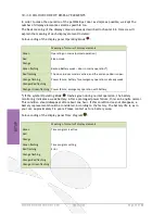
Page 72: ...ode is active and the entrance door is open Orange flashing Power failure battery for emergency operation is already weak Orange Red flashing Orange Green flashing Power failure emergency operation with battery If the symbol Operating Mode flashes green during normal operation the battery monitoring indicates a weak battery After a prolonged power failure this can be quite normal This condition sh...

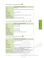
Page 73: ...ed Red Function is forbidden Orange Green flashing During programming Red flashing During programming Orange flashing When motion is detected inside outside Orange Red flashing Orange Green flashing Colour coding of the display panel Access Control Meaning of colours of display elements Green RFID door control is activated Red Error Orange Green flashing During programming Red flashing Error Orang...

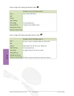
Page 74: ... flashing Programming of brightness level Orange Red flashing Orange Green flashing Colour coding of the display panel Rain Sensor Control Meaning of colours of display elements Green Moisture control is activated battery of sender is OK Red Orange Receiving ok from the rain sensor battery low Green flashing During programming Red flashing No signal reception from the rain sensor Orange flashing O...

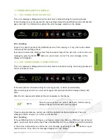
Page 75: ...age is displayed when the door meets an obstacle during the closing process and thus is not able to close If the door meets an obstacle during the closing process it will stop immediately After a waiting period of 2 sec an acoustic signal will sound and another closing attempt will start After the 3rd unsuccessful attempt this error appears on the display NOTE Since the open pet door is a certain ...

Page 76: ...ion on our website In the chapter Frequently Asked Questions you can also find more information on setting the slip clutch and under what conditions you can do this Error handling When the door is still open you have to remove the obstacle When the door is closed again you should check what could have prevented the pet door from closing to avoid this situation in the future Afterwards you confirm ...

Page 77: ...s displayed with a simultaneous alarm signal when the petWALK pet door has lost the door contact in closed state and so has been forced open Error handling If this error occurs the pet door might have been broken up by force and needs to be repaired or replaced You can disable this error message and the alarm signal by pressing the OK button NOTE In very rare cases this alarm can also be triggered...

Page 78: ...mmetrical mushroom cap is used which enables that a manually opened pet door can be turned frontal with a TORX T15 By rotating up to 360 degrees the contact pressure of the door leaf can change The pin in the hinge is loose In the production process the bolt which keeps the door leaf in the hinge is pressed into the hinge Over the years these bolts can loosen So you should check the tightness of t...

Page 79: ...ode symbol means that the battery is low The battery charge status is continuously monitored during operation After a prolonged power failure this can be quite normal The flashing light should disappear after about one hour If this condition does not disappear a battery replacement should be arranged The operation of the pet door is not disturbed but you do not know when the battery will fully col...

Page 80: ...e during usage www petwalk at In the FAQ s you can find a lot of answers Of course we also gladly answer your requests via e mail Please send your mail directly to info petwalk at or use the contact form on our website We are pleased to assist you personally via phone at 43 2635 66937 If you call outside business hours we will call you back as soon as possible if you leave your name and telephone ...

Page 81: ...d properly at the end of its life Recyclable materials contained in the old unit can be recycled and so you can protect the environment Please contact your local waste disposal company for further information 17 DECOMMISSIONING OF PETWALK PET DOOR NOTE Please depollute the pet door or parts of it environmentally friendly and correctly sorted metal to the respective metal scrap plastic to plastic w...

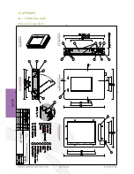
Page 82: ...Petwalk Solutions GmbH Co KG User Guide Page 82 of 88 Petwalk Solutions GmbH Co KG User Guide Page 82 of 88 18 APPENDIX 18 1 TECHNICAL DATA Dimensions Medium ...

Page 83: ...Page 83 of 88 User Guide Petwalk Solutions GmbH Co KG Dimensions Large ...

Page 84: ...g m Thermal conductivity acc DIN 12667 0 028 W m K Mechanics Fully galvanized steel Fittings WK2 Certified fittings from Maco MAYER CO Hardware GmbH Door seals Silicone seals from Helmut Goll GmbH Frame seals EPDM cords Component strenghts when component enclosing installation Standard version 2 10 cm with 2nd spacer 0 5 2 cm with optional tunnel 10 100 cm Thermal conductance calculated Standard 0...

Page 85: ...ternal transponders Necklace Pendant 15 cm to 50 cm Climatic conditions Inside area 0 C to 40 C Outside are 40 C to 85 C Power Supply System Input voltage 90 264 V AC Output voltage 24 V DC Base load 0 2 A Cable length 1 8 m Backup battery 12 V 0 8 A Backup battery time CR 3220 Battery remote control 3 V CR2025 Sensors 2 capacitive motion sensors 2 passive infrared Motion Sensors 1 light sensor 1 ...

Page 86: ...month after knowledge of warrantee case Replacement devices or their components which were replaced in the context of warranty repair shall become the property of Petwalk Solutions GmbH Co KG Warrantor is Petwalk Solutions GmbH Co KG Huber Josef Straße 6 2620 Ternitz Any liability in particular for damages that are not on the device itself is excluded The disclaimer does not apply if liability is ...

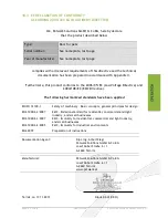
Page 87: ...Directive and 2004 108 EC EMC Directive The following harmonized standards have been applied EN ISO 12100 1 Safety of machinery Basic concepts general principles for design EN 61000 6 3 2007 EN 61000 6 1 2007 EN 61000 6 2 2005 EMC Emission standard for residential commercial and light industry and small businesses EMC Immunity for residential commercial and light industry and small businesses EMC ...

Page 88: ... of 88 18 4 NAME PLATE This nameplate is located on the inside of the outer flange For questions regarding to this equipment please keep the serial number S N and part number A N ready So you help us identify your petWALK pet door The petWALK Team wishes you and your pet a lot of fun with this product ...

Reviews: