ASLD2200 - Instruction Manual
2 Principle of Operation
The ASLD2200 uses a Suspended Solids sensor to detect the density of the sludge & hence the position at which the
density makes a step change (the interface): The instrument moves the sensor to a point that is just above the
interface, (low SS), then lowers the sensor below the interface, (high SS), to confirm the position of said interface. The
control regime operating the motor is then tasked with constantly oscillating the sensor between low & high SS
readings, keeping the sensor at the point of interface. Hence detecting whether there is movement. The numeric
display will show the current value of the interface position in terms of percentage of liquid level in the tank. 0%
represents the bottom, and 100% is the surface the liquid.
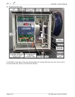
The user is provided with information about the sensor reading by the panel of LED’s on the printed circuit board
assembly (PCBA).
The output of the sensor is divided as shown in the graph below:
The ‘motor’ LED’s will come on once the related sensor LED has been on for 5 seconds and the motor will activate.
The ‘limits’ LED’s will be used when the system reaches either 0 or 100%
The 3 digit LED display will indicate the position of the sludge blanket as a percentage of the depth of the tank. For
example if the tank is 4 metres deep and the display is showing 25%, the sludge blanket is 1 metre from the bottom of
the tank
103370IM Issue 10 Date 19/03/2018
Page 7 of 30
PCBA OF DISPLAY PANEL SHOWING LEGENDS
DISPLAY PANEL SHOWING LEGENDS
INTERFACE
SUPERNATENT
CLEAN
WATER
SUSPENDED SOLIDS
SENSOR
OUTPUT
SENSOR ‘LO’
LED ON
BOTH LEDS
OFF
SENSOR ‘HI’
LED ON


