ASLD2200 - Instruction Manual
Table of Contents
1 Introduction.................................................................................................................................................................. 5
1.1 General............................................................................................................................................................. 5
1.2 Output Signal.................................................................................................................................................... 5
1.3 Limit Relay........................................................................................................................................................ 5
1.4 Manual Conventions......................................................................................................................................... 5
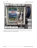
1.5 Mechanical Overview........................................................................................................................................ 6
2 Principle of Operation................................................................................................................................................... 7
3 ASLD2200 Selection.................................................................................................................................................... 8
3.1 Sensor Selection............................................................................................................................................... 8
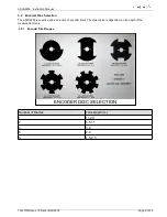
3.2 Encoder Disc Selection..................................................................................................................................... 9
3.2.1 Encoder Disc Ranges................................................................................................................................. 9
4 Control Settings......................................................................................................................................................... 10
4.1 Up and Down Buttons..................................................................................................................................... 11
5 Installation.................................................................................................................................................................. 12
5.1 Location.......................................................................................................................................................... 12
5.2 Electrical Connections.................................................................................................................................... 13
6 Configuration.............................................................................................................................................................. 14
6.1 Sensor Selection............................................................................................................................................. 14
6.2 Depth Range Selection................................................................................................................................... 14
6.3 Links............................................................................................................................................................... 15
7 Calibration.................................................................................................................................................................. 16
7.1 Set Zero.......................................................................................................................................................... 16
7.2 Set Span......................................................................................................................................................... 16
8 Scraper Clearance..................................................................................................................................................... 17
8.1 Bridge Clearance Control................................................................................................................................ 17
9 Outputs...................................................................................................................................................................... 18
9.1 Analogue Output............................................................................................................................................. 18
9.2 Limit Relay...................................................................................................................................................... 18
10 Maintenance............................................................................................................................................................ 19
10.1 General Precautions..................................................................................................................................... 19
10.2 Routine Maintenance.................................................................................................................................... 19
10.3 Removal of the Printed Circuit Board Assembly............................................................................................19
10.4 Sensor replacement...................................................................................................................................... 21
11 Fault Finding............................................................................................................................................................. 22
11.1 Symptom: Digital display changes but does not relate correctly to the sensor position.................................22
11.2 Symptom: The sensor drives to the top limit.................................................................................................23
11.2.1 Fault: Sensor is fouled............................................................................................................................. 23
11.2.2 Fault: Faulty External UP Switch............................................................................................................. 23
103370IM Issue 10 Date 19/03/2018
Page 3 of 30


