ASLD2200 - Instruction Manual
7 Calibration
Calibration is carried out in 2 stages; firstly set the zero point, then the 100% value. As the sensor is going to be
lowered to the bottom of the tank it is important that attention is paid to any hazards such as moving scrapers below
the surface of the tank.
NOTE
: The Zero & 100% potentiometers mounted on the PCBA play no part in the calibration routine.
7.1 Set Zero
Set the rotary switch to ‘motor stop’ and
take the sensor down to the bottom of the
tank by taking loops of cable off the drum.
Once the cable is close to the bottom of
the tank gently raise and lower the sensor
and it will be possible to ‘feel’ the bottom
of the tank. Use the ‘motor up’ position of
the rotary switch to move the sensor such
that it is approximately 25 mm from the
bottom of the tank. Press the Red Zero
push button to set the zero point, it is
sometimes necessary to press this button
a few times to ensure a correct zero
setting.
It is important that the zero point is set
above the bottom of the tank, if the
sensor is allowed to drag on the floor of
the tank damage can occur and there is a
danger that the sensor can become
entangled in the scraper mechanism.
7.2 Set Span
Now use the ‘motor up’ position to bring
the sensor to the water surface. It is
normally advisable to leave the bottom
part of the sensor (approximately 50 mm)
under the surface.
Set the rotary switch to ‘motor stop’ and
adjust the Top Limit potentiometer until
the TOP LIMIT LED comes on (3 digit
LED display should approx be 100)
It is advisable to run the instrument back
down to 0 to confirm that the calibration
has been performed satisfactorily.
Page 16 of 30
103370IM Issue 10 Date 19/03/2018
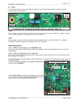
ROTARY
SWITCH
STEP 1 – ZERO CALIBRATION
STEP 2 – SPAN CALIBRATION
DO NOT USE
THESE POTS
FOR SETTING
UP
CALIBRATION


