background image

7

8

1

1

2

4

5

7

3

9

6

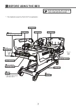
Foot end

Head end

Head end

8

11

WARNING

<Gap related notes>

g

 Watch the gaps.

n

 There are gaps in the bed, side-rail, etc. There is a risk of injury if part of the body (especially the 

head and neck) gets caught in those gaps.

n

 Be especially careful to check a patient who might act in unexpected ways or cannot maintain their 

posture independently.

n

 Pay attention to the following points.

1

 Gap in side-rail

2

 Gap between side-rails (head end/foot end)

3

 Gap between side-rail and board

4

 Gap between side-rail and mattress deck/

mattress (vertical direction)

5

 Gap between side-rail and mattress deck/

mattress (horizontal direction)

6

 Gap inside the board

7

 Gap between board and mattress deck/

mattress

8

 Gap between raised mattress deck and 

board/side-rail

9

 Gap between IV Pole/side-rail spacer/Foot 

spacer/Traction frame and board/side-rail/
mattress deck/mattress

*  The figure shows an example.

1

 BEFORE USING THE BED

Summary of Contents for 7B01001000A3

Page 1: ...r reading this instruction manual store it in a place that can be easily accessed for later reference Users and or patients are requested to report information about any serious incident that occurs within the EU to the regulating authority of the member country of residence Serious incident means any incident that directly or indirectly resulted in may have resulted in or may result in any of the...

Page 2: ...38 Roller bumper 39 Angle indicator 40 Connecting to the power supply 41 Battery excluding PA H 611 PA H 612 PA H 613 PA H 614 42 Attaching and detaching the handheld controller RC 1850E accessory excluding PA H 612 PA H 614 46 Handheld controller hook 47 Connecting the bed communication cable commercially available product PA H 631 PA H 633 only 48 2 FUNCTIONS AND OPERATIONS 49 1 Bed functions 49...

Page 3: ...ies 73 Handheld controller 73 BED Navi 78 IV pole 79 Oxygen cylinder holder 80 Traction frame 82 Orthopedic frame attachment 82 Extension mattress 83 Side rail spacer Foot spacer PA H6 1 PA H612 only 84 Side rail spacer holder 85 Lifting pole 86 Monitor table 87 Bed linen rack 88 Chart holder 89 Nemuri SCAN 1 general medical device body motion sensor 90 4 Peripherals 91 Bedside table 91 Overbed ta...

Page 4: ...to normal manufacturing tolerances Except for special cases words such as approximately and about are omitted in this instruction manual to improve readability n For any queries contact Paramount Bed or your distributor 5 REFERENCE INFORMATION 100 1 Regular inspection and daily maintenance 100 Regular inspection 100 Daily maintenance 101 2 Long term storage and disposal 102 Long term storage 102 P...

Page 5: ...ass index BMI 17 Supported age range 13 years and older Do not use the bed for children aged 12 or under or patient weighing more than 180 kg Intended users Medical professionals patients close relatives of patients and maintenance staff Caregivers is used in this manual to refer to medical professionals and close relatives of patients Part names P 29 P 29 P 40 P 60 to 65 P 40 P 36 P 41 P 41 P 70 ...

Page 6: ... pages where a related explanation is provided This illustration uses the PA H 621 for explanation 125 mm double wheel with resin cover Base frame Accessory attachment hole Patient control panel Leg section Knee section Hip section Head section Side pedal Caster Extension frame Mattress stopper Roller bumper P 39 ...

Page 7: ...ation is provided This illustration uses the PA H 612 for explanation P 29 P 29 P 36 P 41 P 41 P 70 P 30 and 31 P 30 and 31 Headboard Head end side rail Foot end side rail Footboard Accessory rail Night light Power cable CPR lever Main frame Power plug Back of the hip section Battery P 42 ...

Page 8: ...lustration uses the PA H 612 for explanation P 38 P 39 P 32 and 33 P 34 P 69 P 34 125 mm double wheel with resin cover Base frame Accessory attachment hole Leg section Knee section Hip section Head section Side pedal Caster Extension frame Mattress stopper Roller bumper Handheld controller 1 BEFORE USING THE BED ...

Page 9: ...Head end Foot end Head end 8 Applied parts Parts of the bed that in normal use necessarily come into physical contact with the patient for the bed to perform its function Cable storage hooks ...

Page 10: ...ches or cuts or property damage With regard to the items described in Safety precautions Gap related notes see p 11 and 12 are especially important because ignoring them could result in serious life threatening accidents Be sure to read these items to ensure safe and proper use of the bed Be especially careful to check a patient who might act in unexpected ways or cannot maintain their posture ind...

Page 11: ...Foot end Foot end 10 ...

Page 12: ... n Pay attention to the following points 1 Gap in side rail 2 Gap between side rails head end foot end 3 Gap between side rail and board 4 Gap between side rail and mattress deck mattress vertical direction 5 Gap between side rail and mattress deck mattress horizontal direction 6 Gap inside the board 7 Gap between board and mattress deck mattress 8 Gap between raised mattress deck and board side r...

Page 13: ...e independently g Do not crawl under the bed or place your head hands or legs under the bed n A body part could get caught in the gap between the moving parts of the bed and the frame or side rail resulting in injury Check to make sure there are no objects around the bed before operating the bed n Be especially careful to check a patient who might act in unexpected ways or cannot maintain their po...

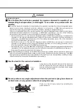
Page 14: ...ay fall off the bed resulting in injury g Do not sit on the side rails headboard or footboard The patient could fall off the bed or fall down or the bed or side rails could be damaged or deformed resulting in injury g When leaving the bed area or taking your eyes off the patient check the mattress deck angle bed height and the state of the side rails and boards n If a physician nurse or attendant ...

Page 15: ... BED Navi accessory Set Patient lock out on the side rail integrated panel or BED Navi accessory to disable the operation of the patient control panel and handheld controller For the setting procedure see p 65 or the instruction manual for the BED Navi accessory Set Selective lock out on the BED Navi accessory to disable individual head knee height inclining operations For the setting procedure se...

Page 16: ...ent lock out on the side rail integrated panel or BED Navi accessory to disable the operation of the patient control panel and handheld controller For the setting procedure see p 65 or the instruction manual for the BED Navi accessory Set Selective lock out on the BED Navi accessory to disable individual head knee height inclining operations For the setting procedure see the instruction manual for...

Page 17: ... fall off the bed through a gap between the bed and side rail resulting in injury g Do not stand on the bed The patient may fall off the bed resulting in injury or the bed may be damaged or deformed In particular be careful with children g Do not spill liquids on the bed n Do not spill liquids on the bed s electrical components such as the connector side rail integrated panel and patient control p...

Page 18: ...ed The use of products other than the specified ones or those from other companies may create unintended gaps cause contact between products or lower stability resulting in injury or failure of the bed For suitable products see p 72 g Keep the bed away from fire Do not use heating appliances such as heaters near the bed This may cause deterioration deformation or fire g Do not use the bed in the o...

Page 19: ...t stand on the side pedal There is a risk of injury due to falling or damage to the bed Power plug and cables g Be careful not to trip over the power cable or handheld controller cable n The power plug or cables may be damaged resulting in electric shock or fire n You may fall over and injure yourself g Do not run cables such as the power cable of the bed or other electrical appliances under the b...

Page 20: ...e cables such as the power cable n The cables may be damaged resulting in electric shock or fire Be careful to prevent cables from getting caught in the moving parts of the bed Do not place heavy objects on cables or apply excessive force to them Do not run over cables with the bed n Request repair or replacement of damaged cables Power plug Grounded outlet g Do not connect or disconnect the power...

Page 21: ... leaked from a broken display panel If the liquid gets on your skin or clothing wash it off with soap and water In particular if the liquid gets into your eyes seek medical attention g Disconnect the power plug from the outlet and turn the battery off when using electronic medical equipment n Using the bed at the same time with electronic medical equipment e g microwave or ultrasonic medical equip...

Page 22: ...eteriorates differently depending on the operating frequency and environment Inspect for loose parts and damage and the operation of the moving parts regularly The continued use of a product in a worn deteriorated condition may result in unexpected injury See p 100 g Request inspection or repair of a damaged bed If the bed is damaged in an earthquake fire flood or any other incident contact Paramo...

Page 23: ...tely with a new one g Check regularly whether the bed can be battery operated or whether the battery replacement time has been reached Replace a battery that has reached the replacement time n The continued use of a battery that has reached the replacement life may cause fluid to leak out of the battery resulting in fire n The estimated replacement time of the battery is 2 to 3 years after purchas...

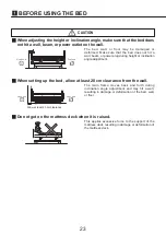
Page 24: ...g height or inclination angle adjustment g When setting up the bed allow at least 20 cm clearance from the wall g Do not get on the mattress deck when it is raised The main frame moves back and forth during inclination angle adjustment and may hit a wall resulting in damage or deformation of the bed wall or floor This applies excessive force to the support of the mattress deck resulting in damage ...

Page 25: ...ght of the persons who will get on the bed must not exceed 180 kg The mattress deck has been lowered all the way and is horizontal flat at the lowest position n If a physician nurse or caregiver often gets on the bed contact Paramount Bed see p 118 or your distributor for regular inspection of the bed g Do not apply a load exceeding the safe working load on the bed The bed may be damaged or deform...

Page 26: ...ee p 69 and p 73 to 77 g Do not apply a spray type insecticide directly to the bed The solvents contained in the insecticide may damage discolor or dissolve the casters or other resin parts of the bed Furthermore damaged or dissolved parts may cause accidental injury g To avoid possible malfunctions avoid installing in the following locations n Locations exposed to direct sunlight n Locations expo...

Page 27: ...r to the instruction manual KOHKIN SIAA mark This is a 2D Code GS1 DataMatrix that encodes the UDI Unique Device Identifier required by the Unique Device Identification System designed to adequately identify devices through distribution and use Type B applied part Symbol Description Protective ground mark International protection code Safe working load Maximum user weight Product weight Maximum we...

Page 28: ...s Not minimum height USB Handheld controller standard product Side rail integrated panel Patient control panel 1 BEFORE USING THE BED Symbol Description Cardiac Chair motion up down Head and knee coordinated up down Trendelenburg reverse Trende lenburg Head up down Knee up down Symbol Description Head and knee coordinated up down Head up down Symbol Description Knee up down Height up down ...

Page 29: ...devices through distribution and use Refer to the instruction manu al Serial number Lot number Medical device This product is a medical device or an accessory for medical device in Europe and may be such a device in some countries and regions depend ing on their regulations An accessory for medical device is required to be labeled as Medi cal Device under medical device regulations in Europe CE ma...

Page 30: ...of whether the board stoppers are set to the unlocked or locked position Detaching 1 Set the board stoppers to the unlocked position 2 locations 2 You can detach the headboard or footboard by holding the grips of the headboard or footboard and pulling it straight up CAUTION n When attaching the headboard or footboard make sure that the board stoppers are locked If they are not locked the board may...

Page 31: ...ause this makes it easier for the patient to roll over them and fall which may result in injury n Do not hang your legs over a side rail while it is lowered The bed may tip over resulting in injury n When raising a side rail make sure that the lock is engaged If the lock is not fully engaged the side rail may go down unexpectedly and the patient may fall off the bed resulting in injury n Be carefu...

Page 32: ... rail and push it to the back toward the center of the bed 2 While pushing it to the back use the other hand to pull the operation lever toward you and while supporting the side rail lower the side rail until it stops Grip Operation lever Locked state Unlocked state Release Guard Release Guard Recess Operation lever Release Guard Operation of the operation lever can be disabled by pulling up the R...

Page 33: ...n them either clockwise or counterclockwise to unlock 2 Hold the extension frame and pull it toward you a little 3 Turn the frame stoppers to the locked position and set them to the slide state half engaged state 4 Hold the extension frame again and pull it toward you until there is a click and the frame stoppers become locked in place 5 Lightly push the extension frame to make sure that it is sec...

Page 34: ...il there is a click and the frame stoppers become locked in place 6 Lightly pull the extension frame to make sure that it is securely locked WARNING Do not put your hand foot or knee on the edge of the extension mattress accessory Since there is no support you may lose your balance and fall over resulting in injury CAUTION n When storing the extension frame do not put your arms or legs between the...

Page 35: ... direction Green Orange g Locking 4 casters Push down the orange side of the pedal to lock the swivel and rotation of all 4 casters g Unlocking 4 casters Return the pedal to the horizontal position to unlock the swivel and rotation of all 4 casters g Locking steering straight forward movement Step on the green pedal to lock swiveling of caster A in the straight forward movement direction This help...

Page 36: ...leg section switching lever locks and the foot end will be in the raised state 3 To lower the foot end lift up the leg section switching lever with one hand while supporting the leg section end with your other hand and lower the leg section slowly You can also lower the foot end by performing the knee down operation while the foot end is raised to lower the knee section to the lower limit Note Whe...

Page 37: ...al CAUTION Do not apply a load of 3 kg or more to an accessory rail This may damage or deform the accessory rail Note n Since the attachment method and dimensions of commercial drainage bags differ by man ufacturer use those suitable for the bed n When hanging a drainage bag take care to prevent the bag or tube from getting caught when operating the bed or side rail n When hanging a drainage bag t...

Page 38: ...ate the bed with restraint belts fastened The restraint belts may apply pressure to the patient resulting in injury CAUTION When making a bed or getting into or out of the bed be careful not to put your hand or fingers in the hole of a restraint holder by mistake There is a risk of injury Restraint holders on the mattress deck side on the left and right of the mattress deck 1 BEFORE USING THE BED ...

Page 39: ...tal of 4 locations They can be used to attach suitable products such as an IV pole and oxygen cylinder holder Note Note that changing the inclination angle of the bed changes the inclination angle of suitable products inserted into the Accessory attachment holes Excluding PA H 611 PA H 612 PA H 613 PA H 614 Accessory attachment hole ...

Page 40: ...9 Roller bumper Roller bumpers are attached to the 4 corners of the bed When the bed is moved they can absorb any impact that occurs when the bed hits a wall or equipment Roller bumper Roller bumper 1 BEFORE USING THE BED ...

Page 41: ...and an inclination angle indicator excluding PA H 611 PA H 612 PA H 613 PA H 614 is located on the outside of the Foot end side rail The head of bed angle and inclination angle can be checked respectively The indicated angle values should be used as approximations Head of bed angle indicator Inclination angle indicator ...

Page 42: ... power consumption requirements of the bed Also firmly insert the power plug into the outlet n When installing the bed place it where connecting and disconnecting the power plug will not be blocked n After use disconnect the power plug from the outlet For a model with a battery also turn the battery off Wind the power cable around the cable storage hooks before moving the bed Using the cable stora...

Page 43: ... into or disconnected from the outlet To stop battery powered operation press the power OFF button n If the battery has been over discharged the power supply automatically turns off The battery is located under the main frame at the head end of the bed Note When replacing the battery remove the cover When attaching the cover pay at tention to its orientation The illustration shows the bed with the...

Page 44: ...le the safe working load is applied on the bed at an ambient temperature of 25 C However the number of up and down movements varies depending on the operating frequency and environment and stor age condition of the battery n BED SPEED is slower than when operating the bed while the power plug is inserted into the outlet except in the event of a power failure In addition the speed varies depending ...

Page 45: ...r 3 9 sec onds blue Remaining battery power is insufficient Buttons on the side rail integrated panel BED Navi accessory handheld controller 1 and handheld controller accessory do not work Recharge the battery immediately The power plug is inserted into the outlet Flashes green on for 3 9 seconds off for 0 1 sec onds Battery is being recharged Lights in green yellow Battery recharging is completed...

Page 46: ...ndicator shows that the remaining power is low or insufficient see p 44 soon after starting bed operation even though the recharge is completed it is time to replace the battery n Check regularly whether the bed can be battery operated or whether the battery replace ment time has been reached Replace a battery that has reached the replacement time g Operating environment It is recommended to use t...

Page 47: ... and turn the battery off before attaching the handheld controller to the bed If the handheld controller is inserted into the bed while the bed is plugged into the outlet the bed could move unexpectedly resulting in injury or bed failure There are handheld controller power outlets located one each on the left and right at the center of the bed main frame Handheld controller power outlet Plug Guide...

Page 48: ...the handheld controller hook it on the top of the Head end side rail Make sure that the operation buttons of the handheld controller face out in order to prevent them from being pressed by the patient Handheld controller of type with a handheld controller Handheld controller RC 1850E accessory Hook Hook Head end side rail Head end side rail 1 BEFORE USING THE BED ...

Page 49: ...ed see p 118 or your distributor Connecting to the nurse call system enables a nurse call to be made at the following times n When BED EXIT ALARM detects a change in the status of the patient For details on BED EXIT ALARM see p 53 to 56 n When the nurse call auxiliary button of the bed is pressed For details on the nurse call auxiliary button see p 62 66 and 67 Connecting the cable 1 Connect the b...

Page 50: ... n Be careful of lines during bed operation Lines may be pulled resulting in injury or damage to the lines or equipment Head up Knee up Head and knee coordination Height adjustment The angle of the head and knee sections and the bed height and Trendelenburg reverse Trendelenburg angle see p 51 can be electrically adjusted with no increments For the operation procedure see p 60 to 67 Head up n You ...

Page 51: ... 81 3 cm 150 mm single wheel with resin cover 38 8 to 83 8 cm g Pause function When lowering the bed an alarm sounds and the movement is stopped when the height from floor to mattress deck top floor height reaches 43 cm to ensure safety Press the down button again to lower the bed to its minimum height while the alarm sounds continuously Lowering a side rail with a floor height of 43 cm creates a ...

Page 52: ...ee the table below to less than 43 cm the bed rises to a height of 43 cm and then performs the Trendelenburg reverse Trendelenburg operation Up Up Down Down 15 15 Note When performing the reverse Trendelenburg operation with the head end of the bed lowered the operation is stopped when the bed becomes horizontal To further perform the reverse Trendelenburg operation press the operation button agai...

Page 53: ...n To firmly maintain a posture when performing the head up operation Cardiac Chair up The Cardiac Chair up operation moves the bed to the position in the table below Operation part Angle of head section a Inclination angle of bed b Angle of knee section c Position 65 15 10 Note The part that moves when pressing the button varies depending on the posture when the operation is started The Cardiac Ch...

Page 54: ... the power plug of the bed to an emer gency power supply Note n This product is just an assisting device to detect out of bed and does not guarantee safety A false notification or absence of notification may occur depending on the motion or lying position of the patient We assume no responsibility whatsoever for any damages resulting from an accident etc n The bed communication cable and relay uni...

Page 55: ...re correct detection may not work and notification may not be made in the following cases n If it takes 4 minutes or more for the patient to get out of the bed or sit up on the bed n If the patient gets out of the bed or sits up on the bed after a heavy object which weighs more than half the patient s weight is placed on the bed n If the patient who is lying at the foot end of the bed sits up SIT ...

Page 56: ...e on patients weighing equal to or more than 40 kg Do not use BED EXIT ALARM on patients less than 40 kg Note False notification n If the notification functions are not set correctly an accidental notification may be made n Notification may be made in the following cases In such a case turn off or pause notifica tion If a person other than the patient gets into or out of the bed If the patient rol...

Page 57: ... of the bed notification is made through the nurse call system If the patient gets out of the bed within 4 minutes after sitting down on the edge of the bed notification is made only when the patient sits down on the edge of the bed to avoid repeated notifications If the patient gets out of the bed after 4 minutes or more have passed after sitting down on the edge of the bed notification is made I...

Page 58: ...aging using a cassette within the range of the diagonal lines in the figure below Supported cassette sizes Size Half 38 8 x 46 4 cm or less Square 38 8 x 38 8 cm or less Thickness 1 5 cm or less Weight 3 5 kg or less Unit cm Note n When performing imaging by raising the head section set the cassette all the way to the back of cassette tray In this case the imaging range will be narrower than the r...

Page 59: ...maged or deformed when the cassette tray is operated n While pulling out the cassette tray do not change the locking lever from the unlocked state Otherwise the lever may be damaged or deformed when the cassette tray is operated 1 Detach the headboard See p 29 2 Pull the locking lever toward you to unlock it Lock Unlock Locking lever 3 Hold the grip and pull the cassette tray all the way out Locki...

Page 60: ...peration resulting in injury or cassette damage or deformation n Do not incline the bed while a cassette is set The cassette may come out resulting in injury or cassette damage or deformation Locking lever unlocked Locking lever locked Push in Grip 6 Hold the grip and slowly push the cassette tray all the way to the back 7 Push the locking lever until it locks into place Cassette position when use...

Page 61: ...neself a body part may get caught in the bed by mistake resulting in unexpected injury When such a person runs the risk of operating the side rail integrated panel by oneself you can use one of the following procedures to limit operation and decrease the chance of injury Set Overall lock out on the side rail integrated panel to disable the operation of the side rail integrated panel For the settin...

Page 62: ...Trendelenburg buttons Adjust the inclination angle of the bed Excluding PA H 611 PA H 612 PA H 613 PA H 614 5 Head and knee coordination buttons Adjust the angle of the head knee sections 6 Cardiac Chair buttons Adjust the angle of the head knee sections and the inclination angle of the bed in Cardiac Chair motion Excluding PA H 611 PA H 612 PA H 613 PA H 614 7 Electric CPR button Flattens the inc...

Page 63: ...the patient control panel and handheld controller accessory 3 Overall lock out button Used to block all bed operations except for electric CPR 4 Night light button Used to turn the night light on g Status indication 1 Battery status indicator lamp Flashing etc indicates the battery status Excluding PA H 611 PA H 612 PA H 613 PA H 614 2 Low height indicator lamp Minimum height lamp turns off otherw...

Page 64: ... 612 PA H 613 PA H 614 Press the button 4 to lower the head end of the bed Trendelenburg Press the button 4 to raise the head end of the bed reverse Trendelenburg Note If the bed is inclined the operation is paused when the bed becomes horizontal To incline the bed further press the button again Head and knee coordination Press the button 5 to raise the head and knee sections Press the button 5 to...

Page 65: ...the nurse call auxiliary button of this product will be used be sure to check the op eration after connecting the bed communication cable Check procedure 1 Press the nurse call auxiliary button 2 Check that the LED lamp above the nurse call auxiliary button turns on and a nurse call is made n If the LED lamp above the nurse call auxiliary button does not turn on and the nurse call is not made when...

Page 66: ...rns on When staff answer the call the LED lamp turns off If the LED lamp does not turn on use the call button unit Patient lock out Press the button 0 to disable the operation of the patient control panel and handheld controller accessory The LED lamp is on when disabled Overall lock out Press the button a to disable all bed operations except for electric CPR The LED lamp is on when disabled Night...

Page 67: ...t may get caught in the bed by mistake resulting in unexpected injury When such a person runs the risk of operating the patient control panel by oneself you can use one of the following procedures to limit operation and decrease the chance of accident caused by incorrect operation Set Overall lock out on the side rail integrated panel or BED Navi accessory to disable the operation of the patient c...

Page 68: ... nurse call auxiliary button does not turn on and the nurse call is not made when the button is pressed see 1 Troubleshooting p 95 to 98 and then check the bed and cable If correct operation is not possible even after taking corrective action stop using the nurse call auxiliary button of this product and use the call button unit n For details on the suitable nurse call system and suitable bed comm...

Page 69: ...times difficult to disconnect the cable plug for the USB device USB plug Pull out the USB plug vertically downward while firmly holding both ends of the USB plug Forcibly pulling the cable may cause disconnection n The USB plug has a front and back Before connecting a device to the USB port check the front and back and do not forcibly connect it The USB port and USB plug may be damaged Note The US...

Page 70: ...o raise the part to operate press the button and to lower it press the button 1 Head and knee coordination buttons Adjust the angle of the head knee sections 2 Head up down buttons Adjust the angle of the head section 3 Knee up down buttons Adjust the angle of the knee section 4 Height up down buttons Adjust the bed height Note n Press the operation button to operate the bed and release the button...

Page 71: ...tion resulting in injury or the bed may be damaged or deformed Lowering the head section with a CPR lever CPR levers are located on the right and left of the head section at the head end 1 Pull the CPR lever 2 If you release the CPR lever back halfway through the head down operation is stopped Note n Sometimes it is difficult to lower the head section due to the weight of the patient or the angle ...

Page 72: ...lease or discontinuation of sales For any queries on suitable products contact Paramount Bed see p 118 or your distributor Suitable product 1 Model No 1 Reference page Handheld controller RC 1850E 73 to 77 BED Navi NS T130AE 78 IV pole KC 56A KC 56B EC 562 IC 56A IC 56B IC 56C 79 Oxygen cylinder holder PC 5038 PC 5116 PC 5117 IC A83 IC A84 80 and 81 Traction frame KA 83U KA 86U PC 5121 82 Orthoped...

Page 73: ...ng in a failure n Do not perform X ray imaging using a cassette tray while an air mattress is installed The X ray imaging results may be affected by reflections of parts of an air mattress Standard mattress Width Length Thickness 860 mm 2000 mm 90 to 150 mm 2 Mattress g Suitable mattress PE 6000 Series PE 6013 PE 6113 PE 6213 PE 7000 Series PE 7013 PE 9000 Series PE 9013 PE 9113 Air Mattresses coc...

Page 74: ...operation at its position n Press two or more operation and set tings buttons simultaneously to stop the operation n If you stopped the operation by press ing two or more buttons simultaneous ly remove your hands from all buttons to perform the operation again g Settings button 5 Settings button Enables you to change the various settings with the operation button g Indicator lamps 6 Power lamp Ind...

Page 75: ... mattress deck top will be higher than the indicated value For the exact dimensions see the table below g Identification embossing can be identified by touching the embossed operation buttons Embossed 3 2 Operation disabled state display Flashes when the pressed operation button is disabled 3 Wrench mark When it is time to replace the handheld controller the wrench mark is displayed in the setting...

Page 76: ...e rail integrated panel to disable the operation of the handheld controller For the setting procedure see p 65 Disconnect the power plug and turn the battery off n Note that if you do not press any button for 20 seconds after pressing the settings button the settings will not be completed and return to their original settings The bed may operate unexpectedly resulting in injury g Switching to the ...

Page 77: ... reverse Trendelenburg operations The operation speed is always Fast Brightness of the setting selection lamp Dark Normal Bright Fast Note n When the bed height be comes lower than the pause height the bed lowers at a slow speed n You cannot operate the Cardiac Chair and Tren delenburg reverse Tren delenburg operations on the handheld controller n Setting the operation sound You can unmute or mute...

Page 78: ...election lamp is switched 3 Press the settings button This completes the setting g Setting procedure WARNING When the setting is completed press the settings button on the back of the handheld controller again to confirm the setting If you do not press the settings button the changed setting is not confirmed and you may be injured by unexpected movement of the bed Note Settings specified using fun...

Page 79: ... footboard with the button side facing the outside of the bed For details on the attachment detachment and operation procedures see the instruction manual for the BED Navi 1 If other than the 125 mm double wheel with resin cover casters are used the height to the mattress deck top will be higher than the indicated value For the exact dimensions see p 113 2 Nemuri SCAN is not designed for sales in ...

Page 80: ...it is not distributed in some regions as well where it is not registered as medical equipment For details on the sales of IV pole contact Paramount Bed see p 118 or your distributor Note Note that the Accessory attachment hole at the foot end moves together when the extension frame is pulled out Model No KC 56A KC 56B EC 562 IC 56A IC 56B IC 56C KC 56B IC 56B and IC 56C have two hooks Hook IV Pole...

Page 81: ... 5 cm and 11 5 cm PC 5117 PC 5038 Be sure to use a 1 000 L oxygen cylinder with a diameter between 14 cm and 15 5 cm IC A84 Be sure to use a 1 000 L to 1 500 L oxygen cylinder with a diameter between 14 cm and 15 5 cm Model No PC 5116 PC 5117 PC 5038 IC A83 IC A84 PC 5116 PC 5117 IC A83 Accessory attachment holes are located at the head end and foot end of the bed in a total of 4 locations Note No...

Page 82: ...he head end of the bed in a total of 2 locations Accessory attachment hole Oxygen cylinder holder IC A84 WARNING C B A Use the oxygen cylinder holder IC A84 at position A in the figure on the left If used in position B or C the bed may become unstable and tip over resulting in injury ...

Page 83: ...hment to the bed Accessory attachment hole This illustration uses the KA 83U model for explanation Orthopedic frame attachment The orthopedic frame attachment can be used for attaching the orthopedic frame KA 86U 1 Insert the orthopedic frame attachment into the Accessory attachment hole on the foot side of the bed 2 Insert a screwdriver into the orthopedic frame and tighten the screw 3 Lightly pu...

Page 84: ...attress IE 52EB IE 52ED is not designed for sales in Europe Also it is not distributed in some regions as well where it is not registered as medical equipment For details on the sales of extension mattress contact Paramount Bed see p 118 or your distributor Model No PE 6410 PE 6420 PE 6411 PE 6421 IE 52EB IE 52ED Extension mattress 3 SUITABLE PRODUCTS ...

Page 85: ...tachment hole at the foot end before use The side rail spacer Foot spacer is not a part of the side rail Foot spacer IC A33321Q is not designed for sales in Europe Also it is not distributed in some regions as well where it is not registered as medical equipment For details on the sales of side rail spacer Foot spacer contact Paramount Bed see p 118 or your distributor Model No PC 5112 IC A33321Q ...

Page 86: ...ientation it may hit the patient resulting in injury You can store the side rail spacer Foot spacer Hang the side rail spacer holder on the footboard outer side Note When the side rail spacer holder is being used the following accessories cannot be attached to the footboard Linen rack PC 5060 Monitor table PC 5119 Oxygen cylinder holder PC 5038 Chart holder IZ C21CH Model No PC 5118 3 SUITABLE PRO...

Page 87: ...sulting in injury g The lifting pole can be used for support to raise the body from the bed by attaching to the bed It can be used for training too 1 Attach the parts of the lifting pole to the bed as shown in figure 2 Inset the arm into the outer pipe 3 Tighten the knob bolt to fasten the arm The arm can be set in three positions as shown in figure by changing the knob bolt positions 4 Pull down ...

Page 88: ...placed over the bed do not place an object on the monitor table The object may fall resulting in injury or in damage to the object CAUTION Attach the monitor table in the correct orientation If the monitor table is lowered when in the wrong orientation it may hit the patient resulting in injury Note When the monitor table is being used the following accessories cannot be attached to the footboard ...

Page 89: ...lting in injury g The bed linen rack can be used for setting the linen temporarily when bedmaking 1 Hang the bed linen rack on the footboard with the rack facing the outside of the bed 2 When using the bed linen rack pull the rack out 3 After using the bed linen rack push the rack to the clip Note When the bed linen rack is being used the following accessories cannot be attached to the footboard S...

Page 90: ...rope Also it is not distributed in some regions as well where it is not registered as medical equipment For details on the sales of chart holder contact Paramount Bed see p 118 or your distributor g The chart holder can be used for setting the charts 1 Hang the chart holder on the footboard with the holder facing the outside of the bed Note When the chart holder is being used the following accesso...

Page 91: ...her large body motions are performed frequently since it is not designed as a device to monitor life threatening events For details see the instruction manual for the Nemuri SCAN 1 You can detect body motions turning over respiration rate pulse rate etc and measure sleep states by placing Nemuri SCAN 1 under the mattress 1 Nemuri SCAN is not designed for sales in Europe Also it is not distributed ...

Page 92: ... table or bed may be damaged or deformed n When moving the bedside table around the bed be careful to prevent the bedside table from hitting the side pedal The bed may operate unexpectedly resulting in accidental injury n The following figure shows the usage range of the bedside table cannot be used If it is used anywhere outside the range shown in the figure below the casters of the bed may be un...

Page 93: ...g position of a patient on the bed side who cannot main tain a sitting position without assistance 1 Sittan and rehabilitation table are not sold in some countries or regions Also it may be classified as medical equipment For details contact Paramount Bed see p 118 or your distributor Model No KF 832LA LB LC LD KF 833LA LB LC LD KF 835LA LB LD KF 813 Model No KF 890 KF 840 Overbed table Sittan KF ...

Page 94: ...be damaged or deformed The bed may hit the foot of the lift or the actuator causing damage or deformation n Do not lock the casters of the lift when the foot of the lift is inserted under the bed If the bed hits the foot of the lift or the actuator during bed operation the lift may fall over resulting in injury or the bed or lift may be damaged or deformed n When inserting the foot of the lift und...

Page 95: ...94 Memo ...

Page 96: ...65 Are two or more handheld controllers accesso ry plugged into the handheld controller power outlets If two or more handheld controllers accessory are plugged into the handheld controller power outlets the bed does not operate Insert only one 46 47 The power lamp on the handheld controller ac cessory is off Is the power plug inserted into the outlet Insert the power plug into the outlet 41 The po...

Page 97: ... Did the patient take an action such as getting out of the bed during bed operation Notification is not made during bed operation even when the patient gets out of the bed or sits up If you consider that the patient may get into or out of the bed during bed operation set Overall lock out 65 Did the patient get out of the bed or sit up slowly If it takes 4 minutes or more for the patient to get out...

Page 98: ... a slight movement even though the pa tient does not sit up 55 Notification is made earlier than the specified monitor ing time Was the monitoring time setting changed while the patient is out of bed Turn off notification and then set the monitoring time again while the patient is lying on the bed Charging of the USB de vice does not start or charging stops premature ly Is the power plug inserted ...

Page 99: ... 98 g Positions of product ID labels Product ID labels are affixed to the right side of the main frame and on the inside of the footboard Footboard Product ID label Affixed to the underside of the board Product ID label ...

Page 100: ...is not restricted by an obstacle The bed was operated for a long time intermittently Leave it for 20 to 38 minutes There is a possibility that a circuit to protect the motor against overheating was activated This is not a failure The bed operation button is held down while operating the CPR lever Release the bed operation button you are holding down U4 The bed operation exceeded the maximum contin...

Page 101: ...k frame or any other parts Board Attachment state See p 29 The board stopper must be locked properly There must not be any significant rattling Caster Traveling There must not be any strange noises when the bed is traveling There must not be any abnormal vibrations when the bed is traveling Caster locking operation See p 34 Proper operation can be achieved The operation must not be overly difficul...

Page 102: ...pochlorite e g Milton It is recommended to disinfect the bed before another patient uses the bed CAUTION n Do not use volatile cleaning solutions such as paint thinner benzine or gasoline or cresol Discoloration or deterioration may result n Do not use disinfectants other than those listed above Damage or deterioration may result n Thoroughly wipe off parts with a damp cloth after using a neutral ...

Page 103: ...0 hPa and 1060 hPa n Do not lean the bed against a wall but store it level on the floor n Be sure to disconnect the power plug from the outlet and bundle the power cable in a location where the cable is not pinched or stepped on n Turn the battery off Product disposal When the A6 Series has reached the end of its usable life dispose of it according to the local rules and regulations A gas spring a...

Page 104: ...e 10 to 40 C when using BED EXIT ALARM 15 to 30 C Humidity 30 to 75 RH Atmospheric pressure 620 to 1060 hPa Transport and storage conditions Temperature 10 to 50 C Humidity 30 to 90 RH Atmospheric pressure 620 to 1060 hPa Service life 8 years based on Paramount Bed data On condition that you perform the specified maintenance and inspection and replace the consumable parts e g casters Materials Hea...

Page 105: ...stment side rail up down operations IEC 60601 2 52 2009 A1 2015 application environments 1 and 2 1 Beds with an X at the end of the part number come standard with an X ray cassette tray 2 Bottom height indicates the height from the floor to the top of the bottom 3 Safe working load Load that can safely use the bed Weight of the user and the total weight of accessories such as mattresses and suitab...

Page 106: ... to 40 C when using BED EXIT ALARM 15 to 30 C Humidity 30 to 75 RH Atmospheric pressure 620 to 1060 hPa Transport and storage conditions Temperature 10 to 50 C Humidity 30 to 90 RH Atmospheric pressure 620 to 1060 hPa Service life 8 years based on Paramount Bed data On condition that you perform the specified maintenance and inspection and re place the consumable parts e g casters Materials Headbo...

Page 107: ...stment side rail up down operations IEC 60601 2 52 2009 A1 2015 application environments 1 and 2 1 Beds with an X at the end of the part number come standard with an X ray cassette tray 2 Bottom height indicates the height from the floor to the top of the bottom 3 Safe working load Load that can safely use the bed Weight of the user and the total weight of accessories such as mattresses and suitab...

Page 108: ...C when using BED EXIT ALARM 15 to 30 C Humidity 30 to 75 RH Atmospheric pressure 620 to 1060 hPa Transport and storage conditions Temperature 10 to 50 C Humidity 30 to 90 RH Atmospheric pressure 620 to 1060 hPa Service life 8 years based on Paramount Bed data On condition that you perform the specified maintenance and inspection and re place the consumable parts e g casters Materials Headboard foo...

Page 109: ...stment side rail up down operations IEC 60601 2 52 2009 A1 2015 application environments 1 and 2 1 Beds with an X at the end of the part number come standard with an X ray cassette tray 2 Bottom height indicates the height from the floor to the top of the bottom 3 Safe working load Load that can safely use the bed Weight of the user and the total weight of accessories such as mattresses and suitab...

Page 110: ... 10 to 40 C when using BED EXIT ALARM 15 to 30 C Humidity 30 to 75 RH Atmospheric pressure 620 to 1060 hPa Transport and storage conditions Temperature 10 to 50 C Humidity 30 to 90 RH Atmospheric pressure 620 to 1060 hPa Service life 8 years based on Paramount Bed data On condition that you perform the specified maintenance and inspection and re place the consumable parts e g casters Materials Hea...

Page 111: ...stment side rail up down operations IEC 60601 2 52 2009 A1 2015 application environments 1 and 2 1 Beds with an X at the end of the part number come standard with an X ray cassette tray 2 Bottom height indicates the height from the floor to the top of the bottom 3 Safe working load Load that can safely use the bed Weight of the user and the total weight of accessories such as mattresses and suitab...

Page 112: ...0 C when using BED EXIT ALARM 15 to 30 C Humidity 30 to 75 RH Atmospheric pressure 620 to 1060 hPa Transport and storage conditions Temperature 10 to 50 C Humidity 30 to 90 RH Atmospheric pressure 620 to 1060 hPa Service life 8 years based on Paramount Bed data On condition that you perform the specified maintenance and inspection and re place the consumable parts e g casters Materials Headboard f...

Page 113: ...stment side rail up down operations IEC 60601 2 52 2009 A1 2015 application environments 1 and 2 1 Beds with an X at the end of the part number come standard with an X ray cassette tray 2 Bottom height indicates the height from the floor to the top of the bottom 3 Safe working load Load that can safely use the bed Weight of the user and the total weight of accessories such as mattresses and suitab...

Page 114: ...ectric shock protection Class 1 Type B Application environment in IEC60601 2 52 2009 AMD1 2015 1 and 2 Protection code IEC 60529 IPX4 Equipment not suitable for use in the presence of a flammable anaesthetic mixture Casters Type Total height cm Height of mattress deck top surface cm 125 mm single wheel with resin cover 76 3 2 1 to 121 3 1 5 35 8 2 1 to 80 8 1 5 125 mm single wheel with iron cover ...

Page 115: ...he user to take relaxation measures such as re arranging or changing the direction of the device WARNING n If accessories transducers or cables other than those specified and sold by the manufacturers of the bed are used as replacement parts for internal components it may result in an increase in emission or a decline in immunity of the bed n Use portable RF communication devices including antenna...

Page 116: ...e to line 0 5 kV 1 0 kV Line to earth 0 5 kV 1 0 kV 2 0 kV Line to line 0 5 kV 1 0 kV Line to earth 0 5 kV 1 0 kV 2 0 kV Voltage dips instantaneous power failure and voltage fluctuation in power supply cable IEC 61000 4 11 0 5 cycle for test level 0 UT Phase at 0 45 90 135 180 225 270 and 315 0 5 cycle for test level 0 UT Phase at 0 45 90 135 180 225 270 and 315 1 cycle for test level 0 UT and 25 ...

Page 117: ...ive RF electro magnetic field IEC 61000 4 3 3 V m 80 MHz to 2 7 GHz 80 amplitude modulation 1 kHz 3 V m 80 MHz to 2 7 GHz 80 amplitude modulation 1 kHz a Field strengths from fixed transmitters such as those of base stations for radio cellular cordless telephones land mobile radios amateur radios AM and FM radio broadcasts and TV broadcasts cannot be predicted theoretically with accuracy To determ...

Page 118: ...m 385 MHz 27 V m 380 to 390 TETRA 400 Pulse modulation 18 Hz 1 8 0 3 28 V m 450 MHz 28 V m 430 to 470 GMRS 460 FRS460 Pulse modulation 18 Hz 2 0 3 9 V m 710 MHz 9 V m 704 to 787 LTE band 13 17 Pulse modulation 217 Hz 0 2 0 3 9 V m 745 MHz 9 V m 780 MHz 28 V m 810 MHz 28 V m 800 to 960 GSM 800 900 TETRA 800 iDen 820 CDMA 850 LTE band 5 Pulse modulation 18 Hz 2 0 3 28 V m 870 MHz 28 V m 930 MHz 28 V...

Page 119: ... maintain the original functions of products is 8 years after discontinuation of manufacturing 3 When you are not sure about the after sales service For any queries please feel free to contact your distributor or to the following address Contact Information Location in Japan Manufacturer Location in Indonesia Manufacturing premises PARAMOUNT BED CO LTD 14 5 2 chome Higashisuna Koto ku Tokyo 136 86...

Page 120: ...Instruction manual edited by Torindo Co Ltd 2021 11 ...

Reviews: