background image

P-53

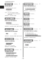
PROGRAMMING (MODE 7)

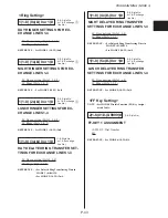
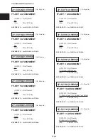
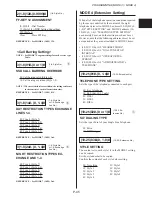
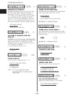
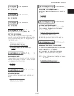
(10-25: Ex-

tension No.)

09(01-16)#-(0-999999)#

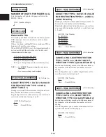
EMERGENCY CALL RESTRICTION
OVERRIDE DATA 1-16 (VALID FOR
RESTRICTION TYPE 0, 1, 2 AND 3 (AL-
LOW TABLE 3)

Restrictions on dialing are cancelled if the maximum 6-
digit number set here matches the number of dialing.
*Exceed dialing data are ignored not send out through

the Exchange line.

0-999999: Dial Number
999 (DATA1)
112 (DATA2)
None (DATA3-16)
Clear      : Press FF5 Key

When all of the telephone operation conditions required
by the user are satisfied by the content of the eight
telephone styles set in MODE 3, the following ad-
dresses need not be set:

• (10-25)01#-(0 or 1)# “SSD CALL BARRING OVER-

RIDE”

• (10-25)1n#-(001-4)# “DAY RESTRICTION TYPES

EXCHANGE LINE 1-4”

• (10-25)2n#-(0 or 1)# “NIGHT RESTRICTION

TYPES EXCHANGE LINE 1-4”

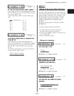
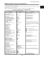
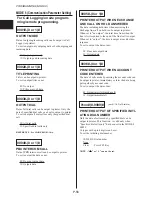
(10-25)01#-(0 or 1)#

C

SSD CALL BARRING OVERRIDE

Sets whether or not to override SSD toll restriction.

0#: Call Barring valid
1#: Call Barring overriden

NOTES : • When restriction is overridden, the setting

conforms to the content of each toll restriction
class.

• See MODE 7 “Program settings for each service

type Table”.

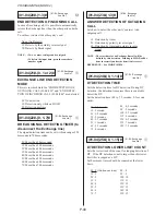
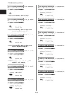
(10-25)1x#-(0, 1-4)#

C

DAY RESTRICTION TYPES EXCHANGE
LINE 1-4

Sets which type fall under for day mode.

0#: Type 0 (Intercom calls only)
1#: Type 1 (Incoming calls only)
2#: Type 2 (Local calls only)
3#: Type 3 (Long distance calls, restricted by area)
4#: Type 4 (No restrictions)

NOTE : See MODE 7 “Program settings for each service

type Table”.

(10-25)2x#-(0, 1-4)#

C

NIGHT RESTRICTION TYPES EX-
CHANGE LINE 1-4

Sets which type fall under for night mode.

0#: Type 0 (Intercom calls only)
1#: Type 1 (Incoming calls only)
2#: Type 2 (Local calls only)
3#: Type 3 (Long distance calls, restricted by area)
4#: Type 4 (No restrictions)

NOTE : See MODE 7 “Program settings for each service

type Table”.

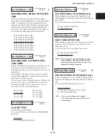
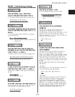
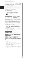
70nn#-(0 or 1)#

C

2-DIGIT RESTRICTION (VALID FOR
RESTRICTION TYPES 1, 2)

Dialing is restricted if the maximum 2-digit number (00
to 99) set here matches the number at start of dialing.
In the initial setting (1#), prohibiting 00-09 allows you
to prohibit trunk transmissions in restriction types 1 and
2.

0#: Not restricted (10-99)
1#: Restricted (00-09)

(01-16: Data No.)

(10-25: Extension No.,

x=1-4: Exchange line

No.)

(10-25: Extension No.,

x=1-4: Exchange line

 No.)

(nn=00-99: 2-digit number

to be restricted)

Summary of Contents for VoiceSonic VB-9411AD

Page 1: ...Operation Installation Programming Installation Programming Operation www voicesonic com Phone 877 289 2829 Panasonic Telephone Systems Panasonic VB 9411AD Panasonic VB 9411AD VB9411AD VB 9411AD 9411AD ...

Page 2: ...turing methods warrant The software and hardware described in this document may be used or copied only in accordance with the terms of the license pertaining to said software or hardware Reproduction publication or duplication of this manual or any part thereof in any manner me chanically electronically or photographically is prohibited without permission of the Matsushita Communication Industrial...

Page 3: ... Contrast Telephones with Alphanumeric LCD Only O 10 Ringing Volume O 10 Speaker Volume O 10 BGM Volume O 10 Making an Exchange Line Call O 11 Making a Call O 11 Using the LINE Key O 11 Line Group Dial O 12 Prime Line Preference O 12 Direct Exchange Line Access O 12 Dial Exchange Line Access O 13 On Hook Dial O 13 Last Number Redial O 14 Save Dial O 14 Speed Dial O 15 ONE TOUCH Key Personal Speed ...

Page 4: ...ive Hold O 24 Exchange Line Hold O 24 Intercom Hold O 24 System Hold O 25 Supervised Transfer O 25 Unsupervised Transfer O 25 Trunk to Trunk O 26 External Conference O 26 Intercom Three Party Conference O 27 Intercom Transfer O 27 Other Useful Features O 28 FF Key O 28 Privacy Release O 29 Sending a Timed Break Signal O 29 Alarm O 29 No Answer O 30 DND Do Not Disturb O 30 Absence Message O 30 Call...

Page 5: ...Station Lock Out O 45 Changing Date and Time O 46 Alphanumeric Character Assignment O 47 Operator Features O 48 Operator s Phone O 48 Day Night Mode Switching O 48 Temporary Mode Change Lunch Mode O 49 Recall Timer for Operator O 49 DSS Console O 49 Optional Features O 50 External Paging O 50 Power Failure O 50 Sensor O 50 Doorphone O 51 Door Opener O 51 Background Music BGM O 52 Headset Connectio...

Page 6: ...ronment this product may cause radio interference in which case the user may be required to take adeguate measures 2 This apparatus must be installed in accordance with BS6701 and general approval NS G 23 L 100005 This is a condition of the approval and any installation which does not comply with the above will invalidate the approval status of that particular installation 3 This equipment require...

Page 7: ...CDR Calling Detail Record Same as Call Logging CF Call Forward CW Call Wait DISA Direct Inward System Access DND Do Not Disturb DPSLT Dial Pulse Type SLT DSS Direct Station Selector DT Dial Tone DTMF Dual Tone Multi Frequency EXT Extension FF key Flexible Function key IDT Intercom Dial Tone INT Intercom LCD Liquid Crystal Display LCR Least Cost Routing LED Light Emitting Diode LRB Loud Ringing Bel...

Page 8: ...osses are as follows Port Type PA1 1AS ITS Port usage 2 wire PSTN exchange line without DDI 2 wire PBX extension Loop calling unguarded clearing MF tone or loop disconnect signalling Timed break recall 2 wire analogue speechband apparatus MF tone or loop disconnect signalling Timed break recall Panasonic SBS key telephone Type of circuit TNV SELV Port description Analogue PSTN Port Port for power ...

Page 9: ...PBX system Timed break recall is available to work with another call routing apparatus 8 Ring eqivalent number REN REN for exchange line port PA1 is 3 9 Line feeding Line feeding from 1AS ports to telephones is derived internally from SBS the Central Control Unit CCU The SBS is not a through fed system Maximum 30mA current is supplied to extension apparatus 10 Recommended extension apparatus When ...

Page 10: ...imed Break signal while talking on an exchange line t REDIAL key For redialing the last exchange line number dialed y MEMORY key For assigning speed dial numbers and making exchange line calls with SSD codes q w MIC 9 10 11 12 5 6 7 8 DND CF INT 1 2 3 4 5 6 7 8 9 0 FL R LINE VOLUME MIC CONF 1 2 3 4 REDIAL MEMORY ON OFF HOLD GHI PQRS JKL TUV ABC DEF MNO WXYZ i o e 7 0 u y t 6 8 9 1 2 r 4 3 5 95 6 9...

Page 11: ... to 10 indicate the number of ONE TOUCH keys 90 to 99 indicate PSD codes 6 DND CF INT LED Lights up in green when Do Not Disturb or call forward has been set Also lights up in red when you make an intercom call flashes quickly when you have an intercom call on hold and flashes slowly when you receive an intercom tone call 7 MIC LED Indicates the MIC key has been pressed to turn on the built in mic...

Page 12: ...y of five different levels It becomes louder when the right side of the VOLUME key is pressed and softer when the left side is pressed When Ringing VOLUME When not Ringing ON OFF MEMORY 9 VOLUME Speaker Volume You can set the speaker volume including the voice call receiving volume to any of five different levels It becomes louder when the right side of the VOLUME key is pressed and softer when th...

Page 13: ...r Long Speech Alarm The alarm beeps after you have been speaking for 2 min and 30 sec Afterwards it beeps every 3 min This feature requires programming and only available for key telephones Account Code This system can record a separate account code for each client Each account code can be up to 10 digits long If you want to enter an account code and make a call do the following 8 7 1 3 4 6 5 2 0 ...

Page 14: ...ime Line Preference You can automatically access a specific line group without pressing the LINE key You can make a call by picking up the handset or pressing the ON OFF key and dialing a telephone number This feature requires pre programming 1 3 4 6 5 2 0 7 9 8 Telephone Number Direct Exchange Line Access You can select an exchange line by pressing an FF key if you have assigned it an exchange li...

Page 15: ...to 884 are assigned to FF key 1 to 4 On Hook Dial You can make a call without picking up the handset Use the handset when you hear the voice from the speaker Using a speakerphone VB 9211DSUK VB 9411DSUK 9411ADSUK allows you to talk through the built in microphone when you hear the voice ON OFF 1 3 4 6 5 2 0 7 9 8 1 3 4 6 5 2 0 7 9 8 Group Code 9 811 812 Telephone 813 or Exchange Line Number Number...

Page 16: ...dials after a certain period of time This feature is available when making an on hook dial call on a key telephone After Auto Repeat Dial is set ON OFF key s led will blink red Save Dial During an exchange line call you can save the telephone number of the outgoing call for later use Unlike the Redial feature the number saved in this way will not be erased when you call another number How ever it ...

Page 17: ...automatically Once you have assigned them you need press only one key or short code in case of SLT to call the desired telephone number For more about ONE TOUCH key assignment refer to the ONE TOUCH key part of the Assignment section in this book To call with a ONE TOUCH Key from key telephone An Extension Number Feature Code or Number with Outside Access Code is As signed ONE TOUCH Key To assign ...

Page 18: ...000 199 To assign See page O 42 SLT See User Guide SLT To confirm the telephone number assigned to an SSD Code Telephones with LCD Only ON OFF MEMORY 1 3 4 6 5 2 0 7 9 8 ON OFF or CONF Key SSD Code 00 To finish 89 or 000 199 LCR When the LCR function has been programmed the LCR function is automatically activated when you make a call When you dial the other party s phone number the cheapest route ...

Page 19: ...ber can be assigned to a ONE TOUCH key or an FF key On Hook Dial You can make a call without picking up the handset Press the ON OFF key instead of picking up the handset Voice Call You can choose between tone call ringing sounds and voice call speaking When making a voice call a splash tone followed by your voice is heard from the telephone receiving your call You can switch voice call to tone ca...

Page 20: ...nswer 6 9 External Paging If an external paging system is connected the system you can also page through it See External Paging in the Optional Features section Paging Group Code The system has 3 paging groups 1 3 Select the group s you want to page LRB Loud Ringing Bell Program setting allows you to transmit the incoming ring tone on an exchange or internal line to external paging FF PGM All grou...

Page 21: ...cedure 4 Message Wait with SLT Sending a message wait from a SBS telephone to a SLT can not be performed In the reversed direction it is available DND Absence Message Call Forward You can leave a message to the extension which is set in DND or absence message However if the extension you reached is set in call forward your message will be forwarded to the other extension specified Busy Tone or Rin...

Page 22: ...Cancellation of Message Wait Message wait is automatically canceled when you return a call To cancel a message without calling back ON OFF 7 9 2 ON OFF To cancel the Message You Left If you want to cancel the message you left call the extension again from the telephone you used to leave it 1 3 2 1 3 2 ...

Page 23: ...hen the extension becomes free it will automatically call you and you can reach the extension just by picking up the handset ON OFF 1 3 4 6 5 2 0 7 9 8 6 ON OFF To Cancel Call wait is automatically canceled when you press the ON OFF key or replace the handset Call Wait with SLT Sending a call wait from a key telephone to an SLT can not be performed However in the reversed direction it is available...

Page 24: ... the LED on an FF key blinks slowly in red If non ringing auto answer is programmed you can answer any calls to your paging group just by picking up the handset Handsfree Answer Back Intercom Key Telephones only You can answer an intercom voice call without picking up the handset You can talk through the built in microphone when its LED lights You can also use the handset if you pick up MIC MIC LE...

Page 25: ...ime reminder calls or perform call back for other extensions 7 0 Direct Call Pick up You can answer calls to other extensions not only in your paging group but also in other paging groups using your telephone However you cannot answer an alarm time reminder call or perform call back for other extensions 7 1 3 4 6 5 2 0 7 9 8 Extension Number 10 25 1 3 2 1 4 3 2 FF PGM PGM ...

Page 26: ... Exchange Line Hold Exchange Line Press same which you are Exchange Line using again Hold Recall If a call on hold is not answered within a certain period of time a hold recall tone sounds on the telephone which placed the call on hold Intercom Hold HOLD HOLD Hold Recall Hold recall is not available for intercom hold Brokers Hold When you are talking to an extension with another intercom call on h...

Page 27: ...sed Transfer You can notify a third party extension of an exchange line call on hold before transferring it This feature is useful when the third party is in another room and visual confirmation is not possible HOLD 1 3 4 6 5 2 0 7 9 8 Extension Number 10 25 Unsupervised Transfer You can force transfer an exchange line call to an extension without notification This feature is useful when you know ...

Page 28: ...tion again External Conference You can make a conference call among two exchange lines and one extension or one exchange line and two extensions This feature is particularly useful when making arrangements among three parties or when arranging schedules To Make a Conference Call with an External 3rd Party HOLD 1 3 4 6 5 2 0 7 9 8 CONF Exchange Line Vacant Exchange Telephone Call or Intercom Line F...

Page 29: ...Number 10 25 Intercom Transfer You can transfer an intercom call to another extension by entering Intercom Three Party Conference tempo rarily HOLD 1 3 4 6 5 2 0 7 9 8 CONF Intercom Call Extension Number 10 25 1 4 5 3 2 1 4 3 2 To Hold To Hold Note When having a conference the voice level becomes lower approximately 6dB This is normal operation as the system balances the conference party s speech ...

Page 30: ... it flashes in green When another extension uses the line it stays lit in red Serial Call If extension numbers 10 25 are assigned to FF keys you can terminate the current intercom call and make another intercom call by pressing an FF key This feature is available either when you are talking or when the busy tone is audible Exchange Line Auto Hold If extension numbers 10 25 are assigned to FF keys ...

Page 31: ...he flash function according to the program setting If you press the FL R key while talking on an exchange line or an internal line you can release current call and reseize same line as a new call without returning the handset Alarm You can set an alarm to ring at your key telephone at a specific time Once it has rung the alarm is auto matically canceled If you are using the telephone at the time t...

Page 32: ...navailable for incoming calls Anyone calling your extension will receive a busy signal ON OFF 7 3 ON OFF To Cancel Repeat the procedure Absence Message You can leave a message at your extension saying why you are out and the time you will return To set the Absence Message ON OFF 7 1 1 3 4 6 5 2 0 7 9 8 1 3 4 6 5 2 0 7 9 8 ON OFF Message Code Returning Time 0000 2359 Message Code You can assign fiv...

Page 33: ... forward a Call to an Extension ON OFF 1 3 4 6 5 2 0 7 9 8 1 3 4 6 5 2 0 7 9 8 ON OFF Call Forward Extension Number Code 10 25 Call Forward Code To confirm the Call Forward from an extension assigned Telephones with LCD Only ON OFF 7 2 ON OFF or CONF key To finish 1 4 3 2 Call Forward Code Function 721 All Calls 722 Busy or No Answer 723 On Busy 725 No Answer 1 4 3 2 FF ...

Page 34: ...and can not set the call forward When a telephone is set to forward calls to exchange line you can not use it to make and receive a call The following operations can be carried out even during setting of Call Forward from the exchange line 72 Cancels Call Forward 88x Acquires an extra exchange line x Exchange line No 74nnnn Sets cancels Station Lock Out nnnn ID code When this feature is assigned o...

Page 35: ...8 ON OFF Source extension Target extension No 10 25 No Own extension 10 25 To cancel Follow Me ON OFF 7 7 1 3 4 6 5 2 0 7 9 8 ON OFF Source extension No 10 25 To cancel Follow Me from Operator s Phone and Admistrator s Phone ON OFF 7 7 1 3 4 6 5 2 0 7 9 8 1 3 4 6 5 2 0 7 9 8 ON OFF Source extension Target extension No 10 25 No 10 25 To confirm Follow Me assignment from an extension assigned ON OFF...

Page 36: ...ension and the secretary can notify her manager Preparation At secretary s extension To set Follow Me to secretary ON OFF 7 7 1 3 4 6 5 2 0 7 9 8 1 3 4 6 5 2 0 7 9 8 ON OFF Manager s Own Extension Extension No No 10 25 10 25 To set BLF key of Manager s extension to secretary s extension ON OFF MEMORY 1 3 4 6 5 2 0 7 9 8 HOLD ON OFF FF key Manager s Extension No 10 25 BLF Busy Lamp Field By assigni...

Page 37: ...be programmed with the administrator s phone 1 4 3 2 Class 0 Exchange line calls are prohibited except emergency calls Class 1 Long distance calls are prohibited Class 2 Specific long distance calls are permitted Class 3 International dialing is prohibited Class 4 No restrictions PGM Day Mode and Night Mode A different access level can be programmed for day and night at each extension Station Lock...

Page 38: ... Code Verified ID code entry overrides any toll restrictions placed on an extension By entering a verified ID code you will get an access class to make a call using any extension The extension regains its service class when you hung up To Call 8 7 1 3 4 6 5 2 0 7 9 8 Verified ID code Vacant Exchange 0 9999998 Line FF key Verified ID Code A verified ID code is a 7 max digit code programmed with the...

Page 39: ... also program to assign a feature to an FF key using the administrator s phone If four exchange lines are accommodated FF1 to FF4 is fixed as the exchange line key 1 to the exchange line key 4 To confirm a feature assigned Telephones with LCD Only ON OFF ON OFF or CONF key FF Key To finish To cancel a feature assigned ON OFF MEMORY HOLD ON OFF FF Key to cancel FF Key Features and LED LED lights to...

Page 40: ...p 70 O 23 Headset Mode Setting Cancellation 51 O 52 INT Call Back with CW 6 O 21 Intercom call 10 25 10 25 Extension No O 17 Line Group Dial 9 or nnn nnn Group No 811 813 O 12 Lunch Mode Setting Cancellation 54 Available only with the operator s phone or O 49 administrator s phone Message Wait 2 O 19 Message Wait Cancellation 792 O 20 Message Wait Confirmation 79 O 19 Message Wait with Call Back 7...

Page 41: ...MORY 1 3 4 6 5 2 0 7 9 8 1 3 4 6 5 2 0 7 9 8 HOLD ON OFF ONE TOUCH Key Exchange line Number to Assign To store Access Number 9 811 813 To Repeat If you want to assign another ONE TOUCH key repeat the procedure 2 to 6 do not press ON OFF key SLT See User Guide SLT Keys Available for One Touch Dial Assignment PSD Codes and ONE TOUCH Keys PSD codes 90 99 correspond to ONE TOUCH keys 1 10 The left mos...

Page 42: ...FL R key after each character to proceed See page O 47 6 FL R 2 2 2 2 FL R 7 7 7 7 7 7 7 FL R 9 9 9 9 9 9 9 HOLD To Repeat If you want to assign another PSD Name repeat the procedure 4 to 8 do not press ON OFF key To confirm a PSD Name Telephones with Alphanumeric LCD Only ON OFF MEMORY 9 0 to 9 9 ON OFF or CONF key PSD Code Number See Page O 8 To finish O 9 To cancel a PSD Name ON OFF MEMORY 1 9 ...

Page 43: ... Name Define and Extension Name 10 25 1st Letter Forward Next Letter HOLD ON OFF To store Example of Extension Name Entry If you want to assign Mary as an Extension name for example do the following You need press the FL R key after each character to proceed See page O 47 6 FL R 2 2 2 2 FL R 7 7 7 7 7 7 7 FL R 9 9 9 9 9 9 9 HOLD To Repeat If you want to assign another Extension Name repeat the pro...

Page 44: ...MORY 1 3 4 6 5 2 0 7 9 8 1 3 4 6 5 2 0 7 9 8 HOLD ON OFF SSD Code Telephone To store 00 89 or 000 199 Number 3 digit SSD Codes Requires programming to use 3 digit codes 000 199 To Repeat If you want to assign another SSD Code repeat the procedure 3 to 6 do not press ON OFF key To confirm an SSD Code assigned Telephones with LCD Only ON OFF MEMORY 1 3 4 6 5 2 0 7 9 8 ON OFF or CONF key SSD Code To ...

Page 45: ... example do the following You need press the FL R key after each character to proceed See page O 47 6 FL R 2 2 2 2 FL R 7 7 7 7 7 7 7 FL R 9 9 9 9 9 9 9 HOLD To Repeat If you want to assign another Extension Name repeat the procedure 4 to 8 do not press ON OFF key To confirm an SSD Name assigned Telephones with Alphanumeric LCD Only ON OFF MEMORY 1 3 4 6 5 2 0 7 9 8 ON OFF or CONF key SSD Code 00 ...

Page 46: ...age Message 1st Define and Message Code 0 9 Letter See O 47 Forward Next Letter HOLD ON OFF To store To cancel an Absence Message assigned ON OFF MEMORY 7 1 3 4 6 5 2 0 7 9 8 CONF HOLD ON OFF Absence Message Code 0 9 Call Wait Message Wait You can modify five system messages for call wait and message wait Both features share the same mes sages Messages can only be modified with the administrator s...

Page 47: ... default is no lockout ID codes can only be entered and confirmed with the administrator s phone To assign an ID Code for Station Lock Out ON OFF MEMORY 8 1 3 4 6 5 2 0 7 9 8 1 3 4 6 5 2 0 7 9 8 HOLD ON OFF Extension Number ID Code To store 10 25 0000 9999 To confirm an ID Code assigned for Station Lock Out Requires Preprogramming and Administrator s Phone only ON OFF 8 1 3 4 6 5 2 0 7 9 8 ON OFF ...

Page 48: ...2 0 7 9 8 1 3 4 6 5 2 0 7 9 8 HOLD ON OFF Hour 00 23 Minute 00 59 To store To Enter the Time Enter the time as HHMM HH hour MM minute using a 24 hour system For example for 5 33PM enter 1733 To set the Date ON OFF MEMORY 3 1 3 4 6 5 2 0 7 9 8 1 3 4 6 5 2 0 7 9 8 1 3 4 6 5 2 0 7 9 8 HOLD Day 01 31 Month 01 12 Year 00 99 To store ON OFF To Enter the Date Enter the date as DDMMYY DD date MM month YY ...

Page 49: ...mes 9 times 1 time 1 1 2 A B C a b c Ä Å A 2 3 D E F d e f Æ Œ D 3 4 G H I g h i Ç G 4 5 J K L j k l J 5 6 M N O m n o Ñ Ö M 6 7 P Q R S p q r s P 7 8 T U V t u v Ü T 8 9 W X Y Z w x y z W 9 0 0 FUNCTION Characters Forward Enter Shift Clear Back Space DESCRIPTION Enter alphanumeric characters See below table Takes a character and moves a cursor to the right Stores characters displayed Switches bet...

Page 50: ...matically at a preprogrammed time However the operator can manually switch the mode and may also set Lunch mode Night mode switching may also be performed with the administrator s phone To change Day Night Mode manually ON OFF 5 2 ON OFF To Return to the Previous Mode Repeat the procedure To turn off Automatic Switching between Modes for a Holiday ON OFF 5 5 1 3 4 6 5 2 0 7 9 8 1 3 4 6 5 2 0 7 9 8...

Page 51: ...ut being answered you can program another phone to ring after a certain period of time You can program the delay time and an exchange line number to forward calls to You can assign a different delayed ring for each of Night Day and Lunch modes Exchange Line Ringing Assignment You can transfer all calls to one extension in any of Night Day or Lunch mode For example you can transfer all calls to the...

Page 52: ...aging unit Power Failure When a power failure occurs you can still use the system for approximately 20 minutes if it has a built in battery However it will not work when the battery is completely discharged Connecting a Power Failure Telephone SLT to the system allows trunk line to cut through directly to SLT during a power failure en abling outgoing and incoming exchange line calls Sensor A senso...

Page 53: ...l from a Doorphone To call the Doorphone A 5 1 To call the Doorphone B 5 2 Door Opener Up to two door openers A and B can be connected to the system You can open a door using the tele phone assigned to the door opener You may open the door where a visitor is located while speaking to the visitor or a specific door A or B without speaking to the visitor To open the Door A B without speaking to a vi...

Page 54: ...ou can use a headset when you need both hands free Disconnect the handset cable from the telephone and connect the headset In headset mode use the ON OFF key to answer a call and do not pick up the handset Use an electret type headset a carbon type headset is not compatible with the system Note that headset mode is disabled as a default Enabling the mode requires preprogramming to prevent false op...

Page 55: ...tension Number 10 25 Automatic Connection to Operator If an outside caller does not dial any number within the pre programmed period of time he she will be automatically connected to the operator To record a Message 1 3 4 6 5 2 0 7 9 8 9 8 1 2 Extention Number 1st 2nd 10 25 Message Message To confirm the Recorded Message 1 3 4 6 5 2 0 7 9 8 9 7 1 2 Extention Number 1st 2nd 10 25 Message Message To...

Page 56: ...play a variety of information concerning calls made using the system by connecting an optional RS 232C interface serial printer or SMDR and computer to the system Call logging includes date and time of calls number of calls exchange line numbers called and an account code if desired Print Out Format EXT COL START DURAT DIAL DATA ACCOUNT Title NN LL DD MM HH NN h dd ss C YYY YYY AAAAAAAAAA CR LF NN...

Page 57: ...tion O 21 INT Call Back O 21 Message Code O 21 Sending O 21 Call Wait Message Wait O 44 Message Cancellation O 45 Message Modification O 44 Class of Service O 35 D Date and Time Change O 46 Date Setting O 46 Time Setting O 46 Day Night Mode Switching O 48 Switching O 48 Cancellation O 48 Dial Exchange Line Access O 13 Direct Call Pick up O 23 Direct Exchange Line Access O 12 DISA OGM Unit VAU O 53...

Page 58: ...ecall Timer for Operator O 49 Ringing Volume Adjustment O 10 F FF Key O 28 O 37 Assignment O 37 Cancellation O 37 Confirmation O 37 Direct Exchange Line Access O 28 Exchange Line Auto Hold O 28 Features Available for FF Key Assignment O 38 INT One Touch Call O 28 Serial Call O 28 Using an FF Key O 28 Flash O 29 Follow Me O 33 Cancellation O 33 Confirmation O 33 Setting O 33 G Group Call Pick up O ...

Page 59: ...ld O 25 System Speed Dial O 16 O 42 SSD Assignment O 42 SSD Call O 16 SSD Cancellation O 42 SSD Confirmation O 16 O 42 SSD Name Assignment O 43 SSD Name Cancellation O 43 SSD Name Confirmation O 43 T Temporary Mode Change Lunch Mode O 49 Setting O 49 Tone Call O 17 Trunk Queuing O 11 Trunk to Trunk O 26 Disconnection O 26 U Unsupervised Transfer O 25 Transfer Recall O 25 Using the Line Key O 11 V ...

Page 60: ...MEMORANDUM ...

Page 61: ... PBX I 10 CONNECTION OF INTERNAL LINES I 11 CONNECTION OF INTERNAL LINES ON HYBRID PORT I 12 CONNECTION OF SINGLE LINE TELEPHONE SLT FOR POWER FAILURE I 13 CLAMPING INSTALLING WIRE I 14 3 WALL MOUNTING OF KEY TELEPHONES I 15 4 CONNECTION OF OPTIONAL UNITS I 16 EXPANSION CARD I 16 DIRECT STATION SELECTOR DSS I 18 CALL LOGGING I F CARD I 20 DOORPHONE DOORLATCH I F CARD I 22 DISA OGM UNIT I 25 BUILT ...

Page 62: ...ne line Key Telephone VB 9211DSUK 6 Key Telephone with LCD and Speakerphone 12 Exchange VB 9411UK 12 Key Telephone line Key 16 Telephone VB 9411DSUK 12 Key Telephone with LCD and Speakerphone VB 9411ADSUK 12 Key Telephone with Alpha numeric LCD and Speakerphone DSS Console VB 9431UK 33 Key DSS Console 2 Optional VB 9260UK 2 Exchange line 8 KT Expansion Equipment Card VB 9261UK 2 Exchange line 8 SL...

Page 63: ...Speed Dial Memory 10 Speed Dial System Speed Dial Memory 90 or 200 Number of Digit 24 Extension Number 2 Digit Battery Back up Time Built in Battery 20 MIN Power Consumption 64 W Central Control Unit 330 x 500 x 99mm 4 3kg Dimension Key Telephone 230 x 186 x 82mm 0 85kg Weight DSS Console 172 x 139 x 44mm 0 8kg DISA OGM Unit 240 x 120 x 45mm 0 4kg Indicates an approximation of battery back up time...

Page 64: ...page I 33 External Paging Adaptor See page I 33 See page I 32 Built in Battery Call Logging I F Card See page I 20 Doorphone Doorlatch I F Card See page I 22 Expansion Card 2 Exchange line 8 KT 2 Exchange line 8 SLT or 8 SLT See page I 16 FG Only red lights the CCU is the standby status Green and red light the CCU is the operating status Only green lights the status that the CCU is operating with ...

Page 65: ...m loose wiring EXT 10 EXT 17 Exchange line 3 and 4 Exchange line 1 and 2 To Exchange line PBX line See page I 9 or DISA OGM Unit Max 2 port See page I 25 or or DSS console Max 2 See page I 18 See page I 11 2 Exchange line 8 KT card 2 Exchange line 8 SLT or 8 SLT card SLT 1 DTMF SLT 1 LD or FAX 1 EXT 18 EXT 25 Expansion Card SLT 8 DTMF SLT 8 LD or FAX 8 NOTE For optional Card Secondary Socket or Ma...

Page 66: ...te electrical noise Conversely this system may interfere with radio receivers and computers Place the CCU at least 10 feet 3 meters away from all other equipment Gas and Airborne Particles To avoid corrosion or oxidation of electrical relay contacts place the equipment in an area free of airborne particles and corrosive gas Humidity Excessive humidity may oxidize the metallic parts and cause error...

Page 67: ...tally install the CCU When installing the CCU vertically install so that the power switch is facing upwards q Use the wall installation template supplied with the CCU packed topmost to determine the installation position w Remove two screws securing the front cover of the CCU e Lift up the front cover and remove the front cover from the three claws at the top of the CCU r Attach four screws loosel...

Page 68: ... marked by the letter E or by the safety earth symbol or coloured green or green and yellow The wire which is coloured blue must be connected to the terminal which is marked with the letter N or coloured black The wire which is coloured brown must be connected to the terminal which is marked with the letter L or coloured red This equipment must be earthed when it is connected to an AC mains Protec...

Page 69: ... two Exchange lines or PBX lines to be connected q Connect Exchange line 1 A to pin No 3 on the DDK connector and Exchange line 1 B to pin No 4 w Connect Exchange line 2 A to pin No 1 on the DDK connector and Exchange line 2 B to pin No 2 e Connect to Exchange line connector Exchange line 1 Exchange line 2 on the CCU r In the same way connect Exchange lines 3 and 4 on the expansion card WARNING Us...

Page 70: ...case the PBX must be approved as a host PBX system The connection of PBX extension to SBS is made in the same way as PSTN connection and terminated at exchange line ports on the CCU NOTE In this manual T and R on the PCB have been replaced with A and B respectively in the description PSTN Timed Break Type PBX A B SBS ...

Page 71: ...ion connector on the CCU e Connect the L A B and H lines from the DDK connector to the 3 5 2 and 4 terminals of the secondary socket LJU r Connect Key Tel 10 to the modular jack of the secondary socket LJU t In the same way connect Key Tel 11 to Key Tel 17 to the extension connector of EXT 2 to EXT 8 on the CCU NOTE Connect the administrator s telephone on which programming is performed to EXT 10 ...

Page 72: ...nnector w Connect the L A B and H lines from the DDK connector to the 3 5 2 and 4 terminals of the secondary socket LJU e Connect Key Telephone to the modular jack of secondary socket LJU 2 Hybrid ports L A 8 B H L A 7 B H L A 6 B H 1 2 3 4 A B DDK connector SLT LD type or SLT DTMF type To telephone Socket 6 1 Master Socket LJU 1 2 3 6 5 4 2 B 5 A 2 Hybrid ports L A 8 B H 1 2 3 4 L A B H DDK conne...

Page 73: ...nnected to Exchange Line 1 NOTE A SLT connected to PF1 of the CCU is for power failures and cannot be used for other purposes q Connect A to pin No 3 of the DDK connector and B to pin No 4 w Connect A and B lines from the DDK connector to the 5 and 2 terminals of the Master Socket LJU e Connect SLT to the modular jack of the Master Socket LJU NOTE In this manual T and R on the PCB have been replac...

Page 74: ...nit at A shown on the figure below Cut off A using pliers and bundle it with the supplied tie wrap A B B local supplied tie wrap WARNING Do not bundle key telephone lines SLT lines and exchange lines together outside the CCU Distance of 50cm is required between them to assure proper functioning A Cut top part first then bend bottom part to cut off ...

Page 75: ...d with electrical wire cutters and prepare wall mounting holes r Attach the Desk stand to the bottom of the telephone by aligning the tabs and tab guides and sliding the Desk stand into place t Attach two screws at the wall mounting positions at 100 mm or 83 mm intervals and secure at mounting holes A B or A C on the Key telephone NOTE When securing at mounting holes A A A A A B B B B B the pitch ...

Page 76: ...tor cable from the expansion card to CN7 of the CCU w Align the protrusion of the expansion card with the installation groove on the CCU and press the both edges A and B of the expansion card to snap it into the place e Connect the connector cable on the expansion card to the ground terminal of the CCU r Use the Expansion DDK connector to add on to the Exchange line Internal line or SLT Connecting...

Page 77: ...DK connector SLT LD type SLT DTMF type or To telephone Socket 6 1 Master Socket LJU 1 2 3 6 5 4 2 B 5 A In case of VB 9261UK VB 9262UK In case of VB 9260UK VB 9261UK NOTE In this manual T and R on the PCB have been replaced with A and B respectively in the description WARNING Use a plier for tighten ing wires to DDK con nectors to prevent from loose wiring SLT lines must not be bundled with key te...

Page 78: ... console See DSS1 PAIR PORT NUMBER 0901 and DSS2 PAIR PORT NUMBER 0902 For details on how to connect the DSS console and the CCU see Connection of Key Telephone page I 16 Fixing of DSS console to key telephone q Stand upright on the Desk stand w Fix the DSS console to the key telephone at the four fixing installation holes provided at the bottom of the key telephone via a fixing plate by fastening...

Page 79: ...CONNECTION OF OPTIONAL UNITS I 19 CCU Extension connector 17 16 15 14 13 12 11 10 Secondary Socket LJU Desk stand Fixing plate DSS Key telephone ...

Page 80: ...onsumption 4mA Installing the Call Logging I F Card WARNING Always unplug the AC plug from the outlet and power off the switch STD BY of the CCU when mounting the Call Logging I F card q Make holes at A B C shown on the figure using pliers w Align the protrusion on the CCU with the hole on the Call Logging I F Card A board and secure by screw w e Align the Call Logging I F Card B board with the in...

Page 81: ...ing I F Card A board Call Logging I F Card B board CCU CN5 q e r w RS 232C to RS 232C If Connecting direct RS 232C to 9Pin DB9 Interface 2 3 4 5 6 7 8 20 22 2 3 7 4 5 1 6 8 9 Personal Computer Recevive Data Transmit Data Request To Send Data Terminal Ready Signal Ground Carrier Detect Data Set Ready Clear To Send Ring Indicator A B C EMI Filter t Call Logging I F Note Dotted lines need not be conn...

Page 82: ...using a DDK connector q Connect Doorphone A to pin Nos 1 and 2 of the DDK connector and Doorphone B to pin Nos 3 and 4 w Connect the DDK connector to CN2 on the Doorphone I F Card e Attach the EMI filter to the cable Connecting the Sensor A Sensor can be connected by using a DDK connector q Short circuit the pins Nos 1 and 2 of the DDK connector w Connect Sensor to pin No 3 of the DDK connector an...

Page 83: ... Power Relay for AC 240 V AC 240 V or Other Power Source CASE2 Door opener operation In the case of AC 240 V or DC 24 V and 1A or more CASE1 Door opener operation In the case of DC 24 V and 1A or less Doorphone B Doorphone A N L E CN4 CN2 CN3 EMI Filter WARNING AlwaysunplugtheACplug from the outlet and power off the switch STD BY of the CCU when mounting the Doorphone Doorlatch I F card WARNING Us...

Page 84: ...of door openers but for Multi Purpose Door opener terminal B also can be used as an external output terminal for receiving calls Program settings are need to use the terminal as an external output terminal for receiving calls See MODE 1 0501 of Programming Manual NOTE Allowable current between each terminal is DC24V 1A Current more than that may cause the damage of the parts of the CCU 1 Multi Pur...

Page 85: ...Per 1 line Message length 16 seconds 2 messages or 32 seconds 1 message Others Power supply 24V Supplied from CCU through Line1 Current consumption 30mA Memory Backup 1 week using Re chargable Litheum Battery Required 2 days to fully charge Mounting the DISA OGM Unit on the wall q Remove the two screws from the DISA OGM Unit and lift off the upper case w Use screws to mount the DISA OGM Unit onto ...

Page 86: ...ents of the Dip switches either q q q q q Turn off the main switch and turn it on again w w w w w Disconnect the main power on the line 1 side and connect it again CCU DDK connector DISA OGM Unit Lithium Battery 1 2 3 ON OFF SW 1 1 2 3 4 5 6 7 8 ON OFF SW 2 SW 2 1 SW 1 1 Line 1 Line 2 Extension connector w q Secondary Socket LJU Secondary Socket LJU 1 2 3 6 5 4 2 B 4 L 3 H 5 A 6 1 1 2 3 4 L A B H ...

Page 87: ...s the maximum 32 seconds Only one message can be recorded 3 Wait for dialling timer Sets how long the unit waits for the caller to dial after completion of OGM before proceeding This setting is set by DIP switches SW2 5 and SW2 6 of SW2 Table 8 SW2 5 SW2 6 Exchange line Response Standby Time Initial setting OFF OFF 2 Seconds OFF ON 6 Seconds ON OFF 10 Seconds K ON ON 14 Seconds Table 9 SW2 1 Dial ...

Page 88: ...g is set by DIP switch SW2 4 of SW2 Table 11 SW2 4 DTMF Detection Time Initial setting OFF 80 m Seconds ON 40 m Seconds K 7 Setting Inhibit Message Recording at an Incoming Call Response There is the possibility that the message may be changed from the outside or from another exten sion So this setting inhibits recording of messages When recording of messages is inhibited abbreviated dial extensio...

Page 89: ...sage Dial 9 7 2 to play the 2nd message while playing the message Either the 1st or the 2nd mes sage Store abbreviated dial extension numbers DISA OGM unit can use 1 digit dialing for faster operation If DISA OGM set 1 digit extension number DIP SW2 7 OFF SW2 8 OFF outside caller need dial only 1 digit 1 to 9 which the DISA OGM unit will automatically convert and transfer appropriate extension 1 S...

Page 90: ...ling abbreviaion number 0 disconnects the DISA line If storing is completed you will hear one beep confirmation tone If storing is failed you will hear error tone two beep sounds To clear or return to the initial data operator call Skip the dialing extension number step e above Dial 9 for operator call If the system is programmed dial 9 as operator call please set non dial call transfer on 9 9 9 i...

Page 91: ...ition on the CCU The built in battery is secured by claws on the CCU w Insert the connector into CN3 on the CCU Replacement of Backup Lithium Battery WARNING Danger of explosion if battery is incorrectly replaced Replace only with the same or equivalent type recommended by the manufucturer Dispose of used batteries according to the manufacturer s instructions Built in battery CN3 CCU w q Lithium b...

Page 92: ...minal for external music on hold MOH Connect the music source to the MOH connector on the CCU using the RCA PIN PLUG NOTE If a tape recorder is connected to the MOH connector place the recorder away from the CCU to prevent interfer ence MOH terminal input impedance 1 5k Ohms maximum MOH terminal input level 150 mV maximum Do not connect speaker terminal with Audio Power Amplifier CCU RCA PIN PLUG ...

Page 93: ...nal Paging Adaptor and External Paging Amplifier Connect an external amplifier and external adaptor to the EPA OUT EPA C connector CN8 inside the CCU The EPA C terminals control the external amplifier NOTE EPA terminal output impedance 600 Ohms EPA terminal output level 20dB CCU CN8 AMP Speaker External Paging Adaptor VA 30966UK To EPA Control To EPA IN 1 4 4 1 CN 2 CN 3 External Adaptor VA 30966U...

Page 94: ...CONNECTION OF OPTIONAL UNITS I 34 MEMORANDUM ...

Page 95: ...ING P 6 ABOUT THE HANDY EXTENSION STYLE SETTING MODE MODE 3 P 6 DATA COPY P 8 DATA TERMINAL PROGRAMMING P 9 PROGRAMMING OUTLINE P 12 4 INITIAL SET TABLE P 13 5 PROGRAMMING P 26 MODE 1 System Setting P 26 MODE 2 Exchange Line Setting P 37 MODE 3 Handy Extension Style Setting P 41 MODE 4 Extension Setting P 45 MODE 5 Ring Setting P 48 MODE 6 Flexible Function Key Assignment P 49 MODE 7 Call Barring ...

Page 96: ...and installation specifications on a programming table form See the Program ming Tables manual 2 INITIALIZINGTHE SYSTEM BEFORE PROGRAMMING WARNING Please do not touch the Power Supply Unit You may be exposed to an electric shock or to dangerously high temperatures Before programming for the first time reset the system as follows 1 Turn off power for Central Control Unit d 2 Move the RAM switch to ...

Page 97: ... Setting Not Available MODE 10 LCR Setting Description Contains feature options that are based system wide Contains feature options on a per Exchange line basis Contains settings of up to eight styles of telephone operation patterns required by users according to feature options on a per station basis Extension Setting MODE 4 Ring Setting MODE 5 Flexible Function Key Assignment MODE 6 and Call Bar...

Page 98: ...odes then the key assigns data and advances to the next higher number port within same address HOLD 0202 0 TONE SEND TIME Advances to the next higher number port 0302 0 TONE SEND TIME MIC 9 10 11 12 5 6 7 8 DND CF INT 1 2 3 4 5 6 7 8 9 0 FL R LINE VOLUME MIC CONF 1 2 3 4 REDIAL MEMORY ON OFF HOLD Enters copies data PSD key PSD1 System Setting Mode PSD2 Exchange Line Setting Mode PSD3 Handy Extensi...

Page 99: ...AL 0302 0 CDR TIME 15 30 Input new address numbers PROGRAMMING GUIDANCE DISPLAY Programming allows various instructional messages to appear on the display thereby making programming easier However the contents of the program may change LCD Display Programming Program the LCD display of the key telephone according to the format shown below Using new Dot Matrix 2 line LCD phone xxxx NNNNNNN CCCCCCCC...

Page 100: ...state MODE 3 to MODE 7 settings can be omitted simply by setting the STYLE SETTING 10 25 03 in the Extension Setting mode MODE 4 Using MODE 3 with the initial set changed If you want to change the initial set state reset only the desired item in the MODE 3 This allows to change the pattern of each style After changing the parameters of MODE 3 MODE 3 to MODE 7 settings can be omitted simply by sett...

Page 101: ... EXCHANGE LINES x 1 4 0 except Ext 10 1 Ring 0 No Ring 1 Ring 0 No Ring 1 1 8 3x DAY DELAYED INCOMING SETTING FOR EXCHANGE LINES x 1 4 0 except Ext 10 1 Ring 0 No Ring 1 Ring 0 No Ring 1 1 8 4x NIGHT DELAYED INCOMING SETTING FOR EXCHANGE LINES x 1 4 0 except Ext 10 1 Ring 0 No Ring 1 Ring 0 No Ring 1 1 8 5x LUNCH DELAYED INCOMING SETTING FOR EXCHANGE LINES x 1 4 0 except Ext 10 1 Ring 0 No Ring 1 ...

Page 102: ...ed previously is copied to the next higher number port by pressing CONF key MODE 1 System settings and some of the MODE 7 Call Barring setting cannot be copied Some data cannot be copied from port to port Text under each address in this manual is noted accordingly CONF Exchange Line 2 0201 1 0202 2 0222 1 Exchange Line 3 0301 1 0302 2 0322 1 VOL VOL Assigns the displayed port s data and moves to t...

Page 103: ...igit ID code Initially not stored IMPORTANT Communication software must be installed to the personal computer to activate On Site Remote Programming Call Logging I F Card must be installed to the CCU to activate On Site Remote Program ming To Enter Remote programming 1 HOLD after picking up an incoming call from Exchange line Personal Computer d 2 6 d 3 Enter programmed 4 digit ID code Initially n...

Page 104: ...e Set Control Z Exit If you enter P P plus return the screen will display the following REMT P VB 9 Programming Prog At the Prog prompt press H The screen will display the menu and Prog prompt again At the Prog prompt press the S key or the Tilde key followed by number of the setting for example 01 for System programming and press return At the 01 Sys prompt press return again The first address in...

Page 105: ...r The Program Mode from Non Administrator s Phone Programming can be performed from telephones other than the administrator s phone by press ing the following button to change the telephone to the temporary programming telephone 1 ON OFF d 2 9 8 d 3 Program ID 4 digit code initial value is 9999 d 4 ON OFF Finish of assigning temporary administrator s phone d 5 Enter the program mode See page P 3 O...

Page 106: ...IMPORTANT C The data copy is available for items with this mark P Power setting is required for items with this mark M Two or more setting can be assigned with this mark POWER SETTING using ON OFF Switch There are four exceptions to programming from the administrator s telephone The following addresses can be only be programmed using the POWER SETTING MODE 1 addresses 0001 EXCHANGE LINE 0313 SLT O...

Page 107: ... 5 Recall after 120 sec 6 Recall after 150 sec 7 Recall after 180 sec 2 Recall after 40 sec 3 Recall after 60 sec 4 Recall after 90 sec 5 Recall after 120 sec 6 Recall after 150 sec 7 Recall after 180 sec Initial setting 2 2 lines 208 initial 010190 0 12 Hour System 1200001 0 No digits dialed Dial 0 8 1 1 digit Dial 9 None No Pause Dial 0 8 1 Pause after the 1st digit Dial 9 1 3 sec pause 0 15 sec...

Page 108: ...formation tone 1 Alarm 0 Extension by voice 1 9 call Exchange line access 0 1 200 3 digits 000 199 1 External music source 0 Does not blink 1 Detects a break signal 1 Picking up the receiver stops alarm ring 0 Inactivate Speaker 1 Exchange line Incoming call 2 Incoming to moni tored extension 1 8 Exchange line No 10 25 Extension No 1 Exchange line incoming call 2 Internal incoming call 3 Doorphone...

Page 109: ... 0 0 125 sec 1 1 sec 2 2 sec 4 4 sec 0 Disable 0 End by call detection Do not use 1 Timer 0 End by call detection 1 MAX 1 minute 2 MAX 2 minutes 4 MAX 5 minutes 5 MAX 10 minutes 6 MAX 20 minutes 7 MAX 30 minutes 8 MAX 40 minutes 0 No interrupt extension 2 Administrator s telephone or Function Assigned extension 0 None 1 1 set 2 2 sets 3 3 sets 5 5 sets 1 125 125 m sec 2 250 250 m sec 1 Lengthen si...

Page 110: ...TOMATIC SWITCH Thursday Night Mode Start 5050 AUTOMATIC SWITCH Friday Day Mode Start 5051 AUTOMATIC SWITCH Friday Night Mode Start 5060 AUTOMATIC SWITCH Saturday Day Mode Start 5061 AUTOMATIC SWITCH Saturday Night Mode Start 5070 AUTOMATIC SWITCH Sunday Day Mode Start 5071 AUTOMATIC SWITCH Sunday Night Mode Start 9009 BUSY TONE DETECTION TIME Initial setting 0 Does not use DSS2 9999 Clear Press FF...

Page 111: ... 7 7 times 8 8 times 0 0 time 1 1 time 2 2 times 3 3 times 4 4 times 5 5 times 6 6 times 8 8 times 1 146 m sec 2 220 m sec 3 293 m sec 4 366 m sec 5 439 m sec 0 10 pps pulse dial 1 125 m sec ON 125 m sec OFF 2 250 m sec ON 250 m sec OFF 1 PBX line 1 Automatic pause 1 Pooled trunk access group 811 2 Pooled trunk access group 812 3 Pooled trunk access group 813 Initial setting 4 4 times 7 7 times 0 ...

Page 112: ...time 0 More than 50 m sec 3 Detection by timer and polarity reverse signal 0 0 5 sec Other settings 1 Control only in Day mode 2 Control only in Night mode 3 Control in both Day and Night mode 0 Cannot accept call forwarding 0 Disable 2 After 30 sec 3 After 45 sec 4 After 60 sec 0 More than 50 m sec 1 More than 100 m sec 2 More than 150 m sec 4 More than 250 m sec 5 More than 300 m sec 6 More than...

Page 113: ...al 1 Handset only 0 Does not answer Style 1 3 7 8 1 Answers Style 4 6 1 Paging group 1 0 No preference 0 9 0 0 No ring Style 2 8 1 Ring Style 1 0 No doorphone ring Style 2 8 3 Doorphone A and B ring Style 1 1 Conversation time displayed 2 Accepts internal calls only Style 2 8 3 Accepts Exchange line and internal calls Style 1 0 Disable Other settings 1 1 2 2 3 3 4 4 5 5 6 6 7 7 8 8 1 1 2 2 3 3 4 4...

Page 114: ... 25 07 PRIME LINE PREFERENCE C 10 25 08 PRIME LINE ACCESS GROUP C 10 25 09 SENSOR ALARM RING C Page P 43 P 43 P 43 P 44 P 45 P 45 P 45 P 45 P 45 P 45 P 46 P 46 P 46 P 46 P 46 P 46 Other settings 0 9999 Dial Number Clear Press FF5 key 2 DSS1 3 DSS2 0 Pulse 1 Style 1 2 Style 2 3 Style 3 4 Style 4 0 No automatic pick up 2 Handset and ON OFF key 1 Answers None Paging group assigned 2 Paging group 2 3 ...

Page 115: ... 1 Rings 0 9999 Dial Number Clear Press FF5 key MODE 5 Ring Setting MODE 4 Extension Setting Address Function 10 25 10 DOORPHONE RING C 10 25 11 CALL DURATION DISPLAY C 10 25 12 10 25 13 Not Available 10 25 14 10 25 15 OFF HOOK SIGNAL C 10 25 16 DATA SECURITY C 10 25 17 HEADSET MODE 10 25 18 DIAL TONE STOP INTERNAL 10 25 19 OPERATOR TELEPHONE 10 25 20 ADMINISTRATOR S TELEPHONE 10 25 0x DAY RINGER ...

Page 116: ...5 key 0 999999 Dial Number Clear Press FF5 key 1 Call Barring overriden 0 Type 0 Intercom calls only 1 Type 1 Incoming calls only 2 Type 2 Local calls only 3 Type 3 Long distance calls restricted by area MODE 7 Call Barring Setting Address Function 0001 PBX INTERNAL CALL RESTRICT VALID FOR RESTRICTION TYPE 0 0002 MAXIMUM NUMBER OF DIGITS DIALED VALID FOR RESTRICTION TYPE 0 1 2 AND 3 0003 DIALING R...

Page 117: ... for IBM computer 165 Character Ñ code for IBM computer 168 Character code for IBM computer 173 Character code for IBM computer 146 Character Æ code for IBM computer 64 Character Œ code for IBM computer 143 Character Å code for IBM computer 0 4800 bps 0 1 bit MODE 7 Call Barring Setting MODE 8 Communication Parameter Setting Address Function 70nn 2 DIGIT RESTRICTION VALID nn 00 99 FOR RESTRICTION ...

Page 118: ...etting MODE 10 Communication Parameter Setting Address Function 1003 DATA LENGTH for CALL LOGGING or PROGRAMMING DATA TERMI NAL 1004 PARITY CHECK for CALL LOGGING or PROGRAMMING DATA TERMI NAL 1102 STOP BIT for REMOTE PROGRAM MING 1103 DATA LENGTH for REMOTE PROGRAMMING 1104 PARITY for REMOTE PROGRAM MING 0xxxx LOOK UP TABLE M 1001 LCR FUNCTION 201m AUTHORIZATION CODE NCC1 m 1 8 Authorization code...

Page 119: ...DE FOR EACH EX Exchange CHANGE LINE TO USE LCR Line No FEATURE NCC2 223m SELECTION OF AUTHORIZA m 1 4 TION CODE FOR EACH EX Exchange CHANGE LINE TO USE LCR Line No FEATURE NCC3 224m SELECTION OF AUTHORIZA m 1 4 TION CODE FOR EACH EX Exchange CHANGE LINE TO USE LCR Line No FEATURE NCC4 3000 BT ACCESS CODE 3001 NCC1 ACCESS CODE 3002 NCC2 ACCESS CODE 3003 NCC3 ACCESS CODE 3004 NCC4 ACCESS CODE 3010 A...

Page 120: ...dialed 1 1 digit 2 2 digits 3 3 digits 5 PROGRAMMING MODE 1 System Setting 0001 1 4 P EXCHANGE LINES To set the number of lines that are available in a system 1 1 line 2 2 lines 208 inital NOTE Turn the power off and on of the CCU after the programming to activate the new settings You may choose to select only some of the lines in a system for Exchange lines leaving the remaining lines free for ot...

Page 121: ... inserts a pause after the Exchange line access number beginning with 0 Here set at which point to insert the pause Example When the Exchange line access number is 0 1 digit Select 1 When an Exchange line connection is made a pause is automatically inserted after the Exchange line access number 0 even if dialing is carried out following the Exchange line access number 0 and the telephone number Wh...

Page 122: ...fter 120 seconds 6 Recall after 150 seconds 7 Recall after 180 seconds 2 275 mseconds 3 2 seconds 4 3 seconds 3 24 seconds 4 32 seconds 0310 1 7 OPERATOR HOLD RECALL TIMER This is a timer of Hold Recall of an operator The timer is activated only when an operator phone holds the call This setting means how long a call is to be placed on hold before hold Recall is activated to an operator 1 Recall a...

Page 123: ... is transferred to the extension If automatic transfer is not programmed see Operating Instruction for information on manual transfer 0 On Hook transfer disable 1 On Hook transfer enable 0404 0 or 1 ONE TOUCH KEY You can dial stored telephone numbers and SSD codes by pressing a single key if the system is programmed for One Touch call 0 One touch call not available 1 One touch call 5 5 seconds 6 6...

Page 124: ...410 0 or 1 INTERNAL TONE VOICE CALL EXTEN SION When an extension is calling an other extension the call be invoked by voice or internal ringing tone 0 Extension call by voice 1 Extension call using internal ringing tone 0411 0 or 1 OPERATOR CALL DIAL You can call an operator from other extension by dialling 0 or 9 To set the operator call dial number to 0 or 9 0 0 call Exchange line Access 9 1 9 c...

Page 125: ...ate the new settings 0420 0 1 or 2 LRB SETTING The LRB Loud Ringing Bell function allows you to transmit the ringing signal to an external paging system when there is an incoming call to a specified exchange line or internal line This setting sets to set the incom ing call to be transmitted to an exchange line or internal line 0 None 1 Exchange line incoming call 2 Incoming to monitored extension ...

Page 126: ...ated as programmed time is set at MODE 1 address 0502 0 or 1 0 0 125 second 1 1 second 2 2 seconds 3 3 seconds REFERENCE See Relay 1 in MODE1 0502 4 4 seconds 5 5 seconds 6 6 seconds 7 7 seconds 0505 0 1 7 MULTI PURPOSE RELAY 2 OPERA TION TIMER Sets the control time when 0 Relay operated as programmed time is set at MODE 1 address 0503 0 or 1 0 0 125 second 1 1 second 2 2 seconds 3 3 seconds REFER...

Page 127: ...L DTMF SENDING TIME While the key telephone and the single line telephone are connected on the intercom line you can send DTMF signals to the single line telephone You can set the transmission time and minimum pause time 0 80 80 mseconds Transmission time Minimum pause time 1 125 125 mseconds 2 250 250 mseconds REFERENCE See MODE 1 0702 and 0703 0702 0 or 1 EXTEND INTERNAL DTMF SENDING TIME MODIFI...

Page 128: ...necessary to use the telephone as an Administrator s Telephone 0 Does not set ID 0000 9998 ID code 9999 Clear Press FF5 Key 0802 0 or 1 SLT HOLD BY RECALL KEY Sets how to hold SLT To set the hold mode by Recall operation or Recall and numbering plan operation 0 Hold by Recall 1 Hold by Recall and numbering plan REFERENCE Numbering plans are as follows Recall 5 Exchange line System Hold or Intercom...

Page 129: ...ing and specifies three manager phones for one secretary Set the extension No of the phone specified for man ager 1 s use with respect to secretary n 10 25 Extension No Clear Press FF5 Key NOTE When setting manager secretary working the Call Forward setting must also be set to the secretary s extension from the manager s exten sion matched to this program setting 20n2 10 25 MANAGER 2 EXTENTION NO ...

Page 130: ...seconds 8 8 times 9 9 times 10 10 times 11 11 times 12 12 times 13 13 times 14 14 times 15 15 times 9010 0 1 15 BUSY TONE DETECTION LOWER LIMIT COUNT Sets the lower limit of the count for judging detection of Busy Tone If the Busy Tone detection count is smaller than this lower limit this is treated as an Ring Back Tone and this is not judged as a Busy Tone Set how many times should be counted as ...

Page 131: ...to 0219 01 04 Exchange line No 01 04 Exchange line No 01 04 Exchange line No 01 04 Exchange line No 01 04 Exchange line No 01 04 Exchange line No 01 04 05 0 1 3 cM POOLED TRUNK ACCESS GROUP 9 0 811 812 and 813 When 9 0 811 812 or 813 is dialed there is an auto matic connection to a vacant line in the trunk groups 0 Pooled trunk access group 9 0 1 Pooled trunk access group 811 2 Pooled trunk access...

Page 132: ...EFERENCE See MODE 1 0302 See MODE 2 01 04 07 01 04 08 01 04 10 and 01 04 23 01 04 Exchange line No 01 04 Exchange line No 01 04 Exchange line No 01 04 Exchange line No 01 04 10 0 1 or 2 c DTMF SIGNAL TIME TABLE AFTER THE CONVERSION The settings for the DTMF signal time are shown below Signal length Pause length 0 320 320 mseconds 1 480 480 mseconds 2 695 695 mseconds REFERENCE See MODE 2 01 04 02 ...

Page 133: ...s 2 5 seconds 3 6 seconds 01 04 16 0 or 1 FL R KEY TYPE Sets the function of FL R key To set to use FL R key as FLASH or TIMED BREAK RECALL 0 FLASH 1 TIMED BREAK RECALL 01 04 Exchange line No 01 04 Exchange line No 4 8 seconds 5 10 seconds 6 12 seconds 7 14 seconds 01 04 Exchange line No 01 04 Exchange line No 01 04 Exchange line No 01 04 Exchange line No 01 04 17 0 or 1 DT DETECTION AT OUTGOING C...

Page 134: ...mseconds 7 More than 700 mseconds 01 04 Exchange line No 8 8 9 9 10 10 11 11 12 12 13 13 14 14 15 15 8 4 5 seconds 9 5 seconds 10 5 5 seconds 11 6 seconds 12 6 5 seconds 13 7 seconds 14 7 5 seconds 01 04 Exchange line No 01 04 23 1 3 ANSWER DETECTION OF OUTGOING CALL Sets how to detect the other party s answer to an outgoing call 1 Detection by timer 2 Detection by polarity reverse signal 3 Detect...

Page 135: ...r ON OFF key REFERENCE See MODE 4 10 25 03 0 1 8 05 0 or 1 AUTOMATIC ANSWER WITHOUT RINGER 0 Does not answer Style 1 3 7 8 1 Answers Style 4 6 REFERENCE See MODE 4 10 25 05 01 04 26 0 1 15 C DT DETECTION UPPER LIMIT COUNT Sets the upper limit of the count for judging detection of DT If the DT detection count is smaller than this upper limit this is judged as a DT Set how many times should be count...

Page 136: ... 09 0 1 8 10 0 1 3 DOORPHONE RING 0 No doorphone ring Style 2 8 1 Doorphone A ring only 2 Doorphone B ring only 3 Doorphone A and B ring Style 1 REFERENCE See MODE 4 10 25 10 2 812 3 813 1 8 Style No C 1 8 Style No C 1 8 Style No C 1 8 Style No C 1 8 Style No C 1 8 Style No C 0 1 8 11 0 or 1 CALL DURATION DISPLAY 0 Conversation time not displayed 1 Conversation time displayed REFERENCE See MODE 4 ...

Page 137: ...ing Transferring Time in MODE 2 01 04 13 See MODE 5 10 25 3n 1 1 8 4x 0 or 1 NIGHT DELAYED RING TRANSFER SETTINGS FOR EXCHANGE LINES 1 4 0 Does not ring Style 2 6 8 1 Rings Style 1 3 5 REFERENCE See Delayed Ring Transferring Time in MODE 2 01 04 13 See MODE 5 10 25 4n 1 1 8 5x 0 or 1 LUNCH DELAYED RING TRANSFER SETTINGS FOR EXCHANGE LINES 1 4 0 Does not ring Style 2 6 8 1 Rings Style 1 3 5 REFEREN...

Page 138: ... Dial Number 60 Paging All Groups Clear Press FF5 Key REFERENCE See MODE 6 10 25 11 2 1 8 02 0 9999 FF KEY 2 ASSIGNMENT 0 9999 Dial Number 882 Clear Press FF5 Key REFERENCE See MODE 6 10 25 02 2 1 8 03 0 9999 FF KEY 3 ASSIGNMENT 0 9999 Dial Number 883 Clear Press FF5 Key REFERENCE See MODE 6 10 25 03 2 1 8 04 0 9999 FF KEY 4 ASSIGNMENT 0 9999 Dial Number 884 Clear Press FF5 Key REFERENCE See MODE ...

Page 139: ...7 8 Style 8 PROGRAMMING MODE 3 MODE 4 1 8 Style No c 10 25 Extension No 10 25 Ex tension No MODE 4 Extension Setting When all of the telephone operation conditions required by the user are satisfied by the content of the eight telephone styles set in MODE 3 address 10 25 03 0 1 8 STYLE SETTING and MODE 4 address 10 25 01 0 1 4 TELEPHONE TYPE SETTING need merely be set and other settings need not b...

Page 140: ...s 10 25 06 1 3 CM PAGING GROUP Sets an extension for Paging groups 1 2 or 3 None No Paging group assigned 1 Paging group 1 2 Paging group 2 3 Paging group 3 NOTE Two or more settings can be assigned To delete the input data press the same data number again 10 25 07 0 1 or 2 C PRIME LINE PREFERENCE This function is used to determine how an unoccupied Trunk Group Exchange line can be accessed 0 No p...

Page 141: ...eadset mode not available 1 Headset mode available 10 25 Extension No 10 25 Extension No 10 25 Extension No 10 25 Ex tension No 10 25 Ex tension No 10 25 18 0 or 1 DIAL TONE STOP INTERNAL Determine whether the internal dial tone is enabled or disabled 0 Disable 1 Enable 10 25 19 0 or 1 OPERATOR TELEPHONE Operator teature activates such as operator call 0 0411 operator hold recall 0310 or operator ...

Page 142: ...oming call to the Exchange line 1 4 is not answered within a specified period in the Day Mode it is possible to set the telephones other than the ringing telephone to ring To set the telephones to ring or not 0 Does not ring 1 Rings 10 25 4x 0 or 1 NIGHT DELAYED RING TRANSFER SETTINGS FOR EXCHANGE LINE 1 4 If an incoming call to the Exchange line 1 4 is not answered within a specified period in th...

Page 143: ...e B Call 52 Exchange Line 88n n Exchange Line Number 1 4 Follow Me Setting 77 nnmm Follow Me Cancellation 77 nn nn Transfer source extension No 10 25 Follow Me Cancellation from operator 77 nnmm mm Transfer target extension No 10 25 or administrator Follow Me Confirmation 77 Follow Me Confirmation from operator 77 nn nn Extension No 10 25 Group Call Pick up 70 Headset Mode Setting Cancellation 51 ...

Page 144: ... 0 9999 FF KEY 2 ASSIGNMENT 882 Clear Press FF5 Key NOTE This assignment cannnot be changed If 2 or more exchange lines are connected 10 25 03 0 9999 FF KEY 3 ASSIGNMENT 883 Clear Press FF5 Key NOTE This assignment cannnot be changed If 3 or more exchange lines are connected 10 25 04 0 9999 FF KEY 4 ASSIGNMENT 884 Clear Press FF5 Key NOTE This assignment cannnot be changed If 4 exchange lines are ...

Page 145: ...ot access Exchange line except emergency call 1 Type 1 Can not access long distance call 0007 00 99 SSD RESTRICTIONS OVERRIDE NUMBER Exchange line calls from SSD numbers are not re stricted even on telephones set for restriction Set SSD number so that calls from SSD number or more up to 89 or 199 for 3 digit system can be made Example If parameter is set to 60 calls from SSD code 60 89 or 160 199 ...

Page 146: ...ou to enable international calls to specific countries in restriction type 3 0 999999 Dial Number None Clear Press FF5 Key 0009 0 99 NUMBER OF DIGITS FOR PAGER CALL Sets the number of digits for the pager call set in the MODE 7 0008 0 99 Number of digits 0 0010 1 4 M ENHANCED TRS This setting can enhance restrictions in order to prevent TRS omissions Here set whether or not to enhance TRS omission...

Page 147: ...l restriction class See MODE 7 Program settings for each service type Table 10 25 1x 0 1 4 C DAY RESTRICTION TYPES EXCHANGE LINE 1 4 Sets which type fall under for day mode 0 Type 0 Intercom calls only 1 Type 1 Incoming calls only 2 Type 2 Local calls only 3 Type 3 Long distance calls restricted by area 4 Type 4 No restrictions NOTE See MODE 7 Program settings for each service type Table 10 25 2x ...

Page 148: ...roup using SSD are overridden or not 0 Accoding to programmed call barring class 1 Override NOTE With the MODE 7 0007 setting the SSD number for overriding SSD must be set 8nn3 0 1 4 SERVICE TYPE SETTING WITH VERI FIED ID CODE Service type can be set to the calls from restricted telephones by entering the verified ID code Set each verified ID code group to one of the following types 0 Type 0 Inter...

Page 149: ...type 1 Valid Specific long distance call permission Cancelling 6 digit restriction type 2 Valid Special inter national call permission Cancelling 6 digit restriction type 3 Valid Valid Valid Valid Emergency dial permission transmission suspended 999 112 Cancelling SSD restriction Valid Valid Valid Specific party registered in SSD permission None Number of digits Valid Valid Valid Valid None Restri...

Page 150: ... Specified dial calls only has been set in the MODE 8 0003 16 types with up to 4 digits can be set To set the initiating dial number 0 9999 Dial number None Clear Press FF5 Key NOTE or can not be set MODE 8 Communication Parameter Setting For Call Logging on site program ming remote programming 0001 0 or 1 OUTPUT MODE Data of outgoing incoming calls can be output to Call Logger or printer To set t...

Page 151: ... 33 254 SPECIAL CHARACTER Ä CONVER SION CODE Uses the special character in names or messages when inputting or outputting during programming using a personal computer Select and set one of character codes 33 to 254 excluding the control code in order to use special characters Set the character code when special character Ä is input 33 254 Setting character code 158 Character Ä code for IBM compute...

Page 152: ...gnals during remote programming 0 No parity check 1 Odd number parity 2 Even number parity 0210 33 254 SPECIAL CHARACTER Å CONVER SION CODE See 0201 SPECIAL CHARACTER Ä CONVER SION CODE for detailed information 33 254 Setting character code 143 Character Å code for IBM computer 1001 0 or 1 BAUD RATE for CALL LOGGING or PROGRAMMING DATA TERMINAL 0 4800 bps 1 1200 bps 1002 0 or 1 STOP BIT LENGTH for...

Page 153: ... 04999 05000 05009 05010 06449 06450 06459 06460 07999 08000 08009 08010 08929 08930 08939 08940 09409 09410 09419 09420 09999 Initial NCC1 BT NCC1 BT NCC1 BT NCC1 BT NCC1 BT NCC1 BT NCC1 Initial BT NCC1 BT NCC1 BT NCC1 BT NCC1 BT NCC1 BT NCC1 MODE 10 LCR Function Setting 0xxxx 0 4 M LOOK UP TABLE Set the look up table so the system knows to select BT British Telecom or any of NCCs when dialling a...

Page 154: ...LECTION OF AUTHORIZATION CODE FOR EACH EXCHANGE LINE TO USE LCR FEATURE NCC2 The authorization code must be assigned to each exchange line to use the LCR feature Change programme as desired by inputting authorization code number 1 8 223 1 4 m SELECTION OF AUTHORIZATION CODE FOR EACH EXCHANGE LINE TO USE LCR FEATURE NCC3 The authorization code must be assigned to each exchange line to use the LCR f...

Page 155: ...99999 5digits No x 1 8 Restriction Dial No nnnnn 00000 99999 5digits No 303x nnnnn NCC3 RESTRICTION DIAL Special codes such as 999 and 112 numbers must not be sent via NCC3 and should be restricted 3031 for dialling 999 and 3032 for dialling 112 are fixed 999 Dial No 1 112 Dial No 2 Restriction dial Clear Dial No 3 8 304x nnnnn NCC4 Restriction Dial Special codes such as 999 and 112 numbers must n...

Page 156: ...fy whether the MF signal conversion for dialling out to NCC It is useful when the system is routed to the system X local exchanger by Lookup table which does not accept MF signal when 132 is sent out in Dial Pulse 0 No convert 1 Convert 5000 4 digits password PASSWORD TO ACCESS MODE 10 It is possible to set a new password to allow access to mode 10 programming NOTE Since the current password is no...

Page 157: ...P 63 PROGRAMMING MODE 10 MEMORANDUM ...

Page 158: ...Matsushita Electric Industrial Co Ltd Central P O Box 288 Osaka 530 91 Japan 7L1100CZAJ Printed in Singapore www voicesonic com Phone 877 289 2829 3DQDVRQLF 7HOHSKRQH 6 VWHPV See More Panasonic Manuals ...

Reviews: