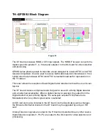
SS Board Explanation
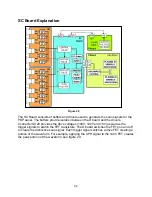
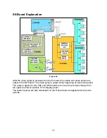
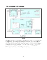
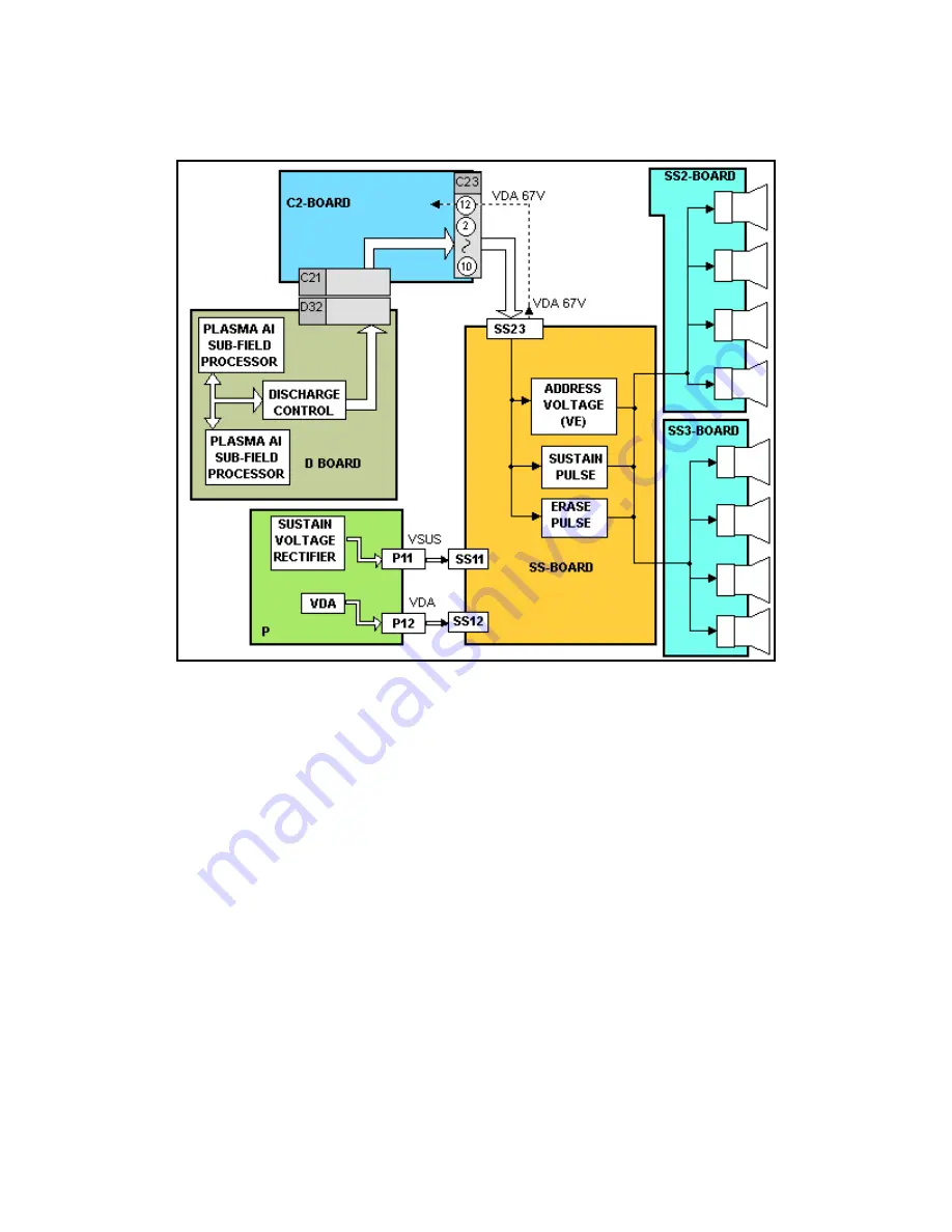
Figure 32
After the video signal is processed on the D board, the sustain and erase pulses are
output to the SS board. The erase pulse is output at the beginning of each scan period.
The pulse is applied to the SS2 and SS3 boards to remove the previous charge from
the upper and lower sections of the display panel.
The sustain pulses are also developed on the D board and are applied after the scan
periods.
37
Summary of Contents for TH-42PX50U
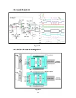
Page 40: ...SC board Waveform Figure 30 SU And SD Board Shift Registers Figure 31 35 ...
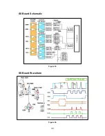
Page 43: ...SS Board Schematic Figure 33 SS Board Waveform Figure 34 38 ...
Page 66: ...Adjustment Volume Locations Figure 53 61 ...
Page 67: ...Test Point Locations Figure 54 62 ...
Page 71: ...Scan and Sustain Drive Waveform Figure 55 Scan and Sustain Drive Check points Figure 56 66 ...

