Signal Process Circuit
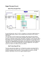
Main Picture Signal Flow
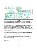
Figure 24
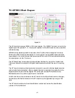
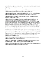
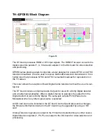
On the DG- Board, the main Y/V, Pb/C, Pr signals are converted to digital data by an
analog to digital (A/D) converter circuit located inside the Global Core IC, IC4018
(ADV7403).
The comb filter in IC4018 converts the composite video signal of the main picture
to Y and C (luminance and chrominance) separated video signals. S-Video, which is
already Y/C separated, simply passes through the comb filter. The chrominance data is
then applied to the Chroma demodulator circuit that separates the color signal into Pb
and Pr data. At the completion of this process, the composite or S-Video signal is now
in the form of a digital 480i component signal. If the incoming video is in the 480p and
1080i format, the Y, Pb, and Pr signals are converted to digital only. The output of
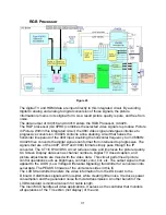
IC4018 is provided to the RGB processor (GC4PRO).
Sub Picture Signal Flow
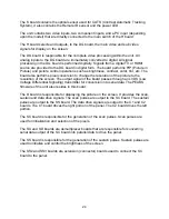
The sub video enters the global core IC, IC4019 for conversion into digital. IC4019
processes the Sub video data for use in the PIP or split screen mode. Operation of
IC4019 is exactly the same as IC4018. The input signals are output to the RGB
processor (GC4PRO) in the form of a digital component signal.
30
Summary of Contents for TH-42PX50U
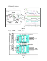
Page 40: ...SC board Waveform Figure 30 SU And SD Board Shift Registers Figure 31 35 ...
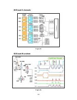
Page 43: ...SS Board Schematic Figure 33 SS Board Waveform Figure 34 38 ...
Page 66: ...Adjustment Volume Locations Figure 53 61 ...
Page 67: ...Test Point Locations Figure 54 62 ...
Page 71: ...Scan and Sustain Drive Waveform Figure 55 Scan and Sustain Drive Check points Figure 56 66 ...

