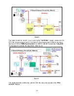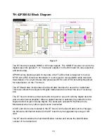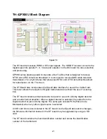
Figure 8
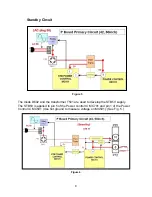
The power control IC, MC701, upon receiving the “
F.STB ON
” voltage, outputs the “PC
PFC ON” control signal at pin 20. This turns on the photocoupler PC503 to provide a
low to pin 2 of the
“STB Power Control”
IC
,
MC501. MC501 outputs the
“relay ON”
control signal to activate the relay K601. (See Fig. 8)
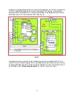
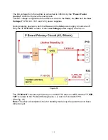
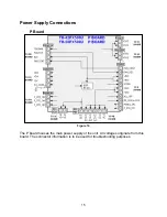
Figure 9
The rectifier MC604 rectifies the 120VAC from the relay and outputs to the
“PFC
Control”
MC602.
10
Summary of Contents for TH-42PX50U
Page 40: ...SC board Waveform Figure 30 SU And SD Board Shift Registers Figure 31 35 ...
Page 43: ...SS Board Schematic Figure 33 SS Board Waveform Figure 34 38 ...
Page 66: ...Adjustment Volume Locations Figure 53 61 ...
Page 67: ...Test Point Locations Figure 54 62 ...
Page 71: ...Scan and Sustain Drive Waveform Figure 55 Scan and Sustain Drive Check points Figure 56 66 ...


