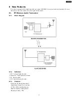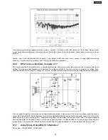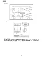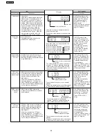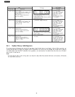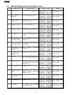
Block diagram:
IC Package Information
Soldering Information
Wave Soldering/Dipping: The maximum permissible temperature of the solder is 260
ー
C; solder at this temperature must not be in
contact with the joints for more than 5 seconds. The total contact time of successive solder waves must not exceed 5 seconds.
Manual Soldering: If the temperature of the soldering iron bit is less than 300
ー
C it may remain in contact for up to 10 seconds. If
the bit temperature is between 300 and 400
ー
C, contact may be up to 5 seconds.
26
SA-HT640WPL
Summary of Contents for SA-HT640WPL
Page 4: ...23 2 Packaging 109 24 Replacement Parts List 110 24 1 Component Parts List 111 4 SA HT640WPL ...
Page 10: ...10 SA HT640WPL ...
Page 16: ...16 SA HT640WPL ...
Page 19: ...8 2 Detail Block Diagram Receiver module 19 SA HT640WPL ...
Page 31: ...31 SA HT640WPL ...
Page 37: ...10 1 Disassembly Flow Chart 37 SA HT640WPL ...
Page 38: ...10 2 Main Components and P C B Locations 38 SA HT640WPL ...
Page 46: ...Step 3 Push tray assembly to the direction of arrow shown 46 SA HT640WPL ...
Page 53: ...14 2 Main P C B 53 SA HT640WPL ...
Page 60: ...SA HT640WPL 60 ...
Page 68: ...SA HT640WPL 68 ...
Page 70: ...70 SA HT640WPL ...
Page 80: ...SA HT640WPL 80 ...
Page 86: ...SA HT640WPL 86 ...
Page 88: ...SA HT640WPL 88 ...
Page 97: ...97 SA HT640WPL ...
Page 104: ...21 3 4 2 Receiver Module P C B 104 SA HT640WPL ...
Page 106: ...23 Explode Views 23 1 Cabinet Parts Location 106 SA HT640WPL ...
Page 107: ...107 SA HT640WPL ...
Page 108: ...108 SA HT640WPL ...
Page 109: ...23 2 Packaging 109 SA HT640WPL ...

