9 Self-Diagnosis and special mode setting
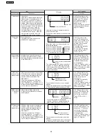
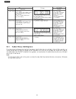
9.1. Service Mode Summary Table
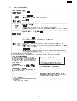
The service modes can be activated by pressing various button combination on the player and remote control unit.
Below is the summary of major checking:
Player buttons
Remote control unit buttons
Application
Note
STOP
0
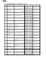
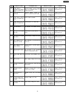
Error code display
(Refer to the section,
“9.3 DVD Self Diagnostic
Function-Error Code”).
5
Jitter checking
(Refer to the section “9.2
Service Mode Table 1”
for more information).
6
Region display and mode
(Refer to the section “9.2
Service Mode Table 1” for
more information).
7
Micro-processor firmware version check
FUNCTIONS
DVD laser drive current check
(Refer to the section
“9.2.1. Optical Pick-up
Self-Diagnosis”).
3
CD laser drive current check
PAUSE
Writing of laser drive current value after replacement of optical
pickup (Do use this function only when optical pickup is
replaced.)
Initialization of the player (factory setting is restored.)
Used after replacement of micro-computer, FLASH ROM IC,
EEPROM.
(Refer to the section “9.2
Service Mode Table 1”
for more information).
8
DVD HDMI Module firmware version check
ENTER
DVD Module Reset.
9.2. Service Mode Table 1
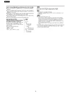
By pressing various button combinations on the player and remote control unit can activate the various service modes for checking.
Special Note:
Due to the limitations of the no. characters that can be shown on FL Display, the “FL Display” button on the remote control unit
is used to show the following page. (Display 1/Display 2).
27
SA-HT640WPL
Summary of Contents for SA-HT640WPL
Page 4: ...23 2 Packaging 109 24 Replacement Parts List 110 24 1 Component Parts List 111 4 SA HT640WPL ...
Page 10: ...10 SA HT640WPL ...
Page 16: ...16 SA HT640WPL ...
Page 19: ...8 2 Detail Block Diagram Receiver module 19 SA HT640WPL ...
Page 31: ...31 SA HT640WPL ...
Page 37: ...10 1 Disassembly Flow Chart 37 SA HT640WPL ...
Page 38: ...10 2 Main Components and P C B Locations 38 SA HT640WPL ...
Page 46: ...Step 3 Push tray assembly to the direction of arrow shown 46 SA HT640WPL ...
Page 53: ...14 2 Main P C B 53 SA HT640WPL ...
Page 60: ...SA HT640WPL 60 ...
Page 68: ...SA HT640WPL 68 ...
Page 70: ...70 SA HT640WPL ...
Page 80: ...SA HT640WPL 80 ...
Page 86: ...SA HT640WPL 86 ...
Page 88: ...SA HT640WPL 88 ...
Page 97: ...97 SA HT640WPL ...
Page 104: ...21 3 4 2 Receiver Module P C B 104 SA HT640WPL ...
Page 106: ...23 Explode Views 23 1 Cabinet Parts Location 106 SA HT640WPL ...
Page 107: ...107 SA HT640WPL ...
Page 108: ...108 SA HT640WPL ...
Page 109: ...23 2 Packaging 109 SA HT640WPL ...

