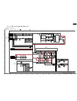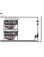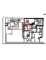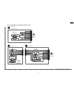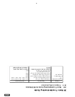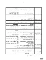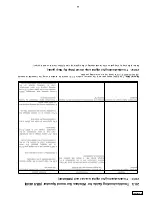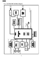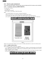
20.1.2. Initialis
ationand
playability
c) C
heck
SD
RA
M , E
EP
RO
M a
nd
Fla
sh
RO
M fo
r s
old
er
*Compare the above w
ith OK condition Module
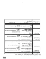
3) Distorted picture or
abnormal sound is heard
during initialisation
2) Picture black and white
only
4) No TO
C/Long
TO
C
5) Disc not spinning
6) Trav
erse not mo
ving
7) Trav
erse and spindle
abnormal mo
ve
me
nt
8) Cannot read disc but
spindle is spinning
- Cannot
read CD
- Cannot
read DVD
9) Block noise during
play
10) DVD Audi
o no audio
output
11) No audio
a) Ch
eck SD
RA
M addresand data bus, CL
K and other
control signals w
av
eform
b) Che
ck
vide
o s
ign
als
c) C
heck
au
dio
DA
C ci
rc
uit
ry
*Compare the above w
ith OK condition Module
a) C
he
ck
mo
tor d
riv
er c
irc
uitr
y (
vo
lta
ge
s)
b) C
he
ck
la
se
r dri
ve
circ
uit
ry
(vol
ta
ge
s a
nd
cu
rren
t)
c) C
heck
LS
I co
nn
ectio
n t
o m
oto
r d
riv
e circ
uit
ry
*Compare the above w
ith OK condition Module
a) C
heck
con
nect
io
n f
ro
m B
ack
end
M od
ule
to
b) C
heck
mo
to
r d
riv
er ci
rc
uit
ry
on
vo
lta
ges
an
d co
ntr
ol
sig
na
ls
Tra
ver
se
un
it
a) C
he
ck
la
se
r dri
ve
circ
uit
ry
(vol
ta
ge
s a
nd
cu
rren
t)
- Che
ck
CD la
se
r dr
ive
- C
he
ck
DVD la
se
r d
riv
e
*Check voltages and LD
current and compare with
OK Module
a) Che
ck
SD
RA
M a
ddr
es
s a
nd data
bus s
ign
al
*Com
pa
re
th
e a
bo
ve
wit
h O
K c
ondi
tio
n M
odul
e
a) C
PP
M k
ey
do
wn
lo
ad
NG
, ch
eck t
es
t p
oin
t f
or
CP
PM
ke
y d
ow
nlo
ad
*C
he
ck
fo
r t
es
t p
oin
t d
am
ag
ed
or b
ro
ke
n pattern
a) Ch
eck audio sig
nal
IC
8421 (5.1ch), IC
8420 (2.1ch)
b) Check audio D
AC
control signals
IC
8051
IC
8111, IC
8151
LB8302
LB8304 , LB8305
LB8301, R8321, R8322, LB8302, R8325, R8326
IC
8421
*Check f
or solder short and/or component
missing/damaged
IC
8251
Q8550,
Q8
551, Q
8552, Q
8560, Q
8561, Q
8562
IC
8001
*Check f
or solder short and/or component
missing/damaged
FP8251,
FP8531,
IC
8251
M +9V
= FP
8101 (P
IN
5/7)
, I
C8251 (
PIN
21)
*Check f
or solder short and/or component
damaged
Q8550,
Q8551,
Q8
552, Q
8560, Q
8561, Q
8562
Q8550,
Q8560,
Q8
561, Q
8562
Q8550,
Q8551,
Q8
552, Q
8560
*Check f
or solder short and/or component
missing/damaged
IC
8051
*Check f
or solder short and/or component
damaged
a) Che
ck
su
pply v
olt
ag
es
(3
.3
V a
nd 1.
2V)
sh
ort
.
a) Check C (chrom
a) signal if using
Composite or S-
Video
b) Check Pb &
Pr signal if using
Component
1) No DV
D lo
go
sc
re
en
saver
(IC8421 / I
C8420) Pin 5 , 6 , 7 &
8
(SURL / SURR / CEN / SW
)
LB
8427 , LB
8428 , LB
8429 , LB
8431
*Check f
or component damaged
(MIXL / MIXR
/ FL / FR
)
LB
8421 , LB
8422 , LB
8425 , LB
8426
c) Ch
eck Z
ero Flag
and A-Mute sig
nal
*Com
pa
re
th
e a
bo
ve
wit
h O
K c
ondi
tio
n M
odul
e
QR8420 , LB8424
*Check f
or solder short and/or component
missing/damaged
b) Che
ck
vide
o s
ign
als
es
pec
ia
lly
Lu
mina
nce
,Y
sig
na
l
LB8301, R8321,
R8322
IC
8051, IC
8611, IC
8651
b) C
he
ck EEP
RO
M
IC
86
11
Prob
lems
Checking P
oin
ts
Ch
ecking components
94
SA-HT640W
PL
Summary of Contents for SA-HT640WPL
Page 4: ...23 2 Packaging 109 24 Replacement Parts List 110 24 1 Component Parts List 111 4 SA HT640WPL ...
Page 10: ...10 SA HT640WPL ...
Page 16: ...16 SA HT640WPL ...
Page 19: ...8 2 Detail Block Diagram Receiver module 19 SA HT640WPL ...
Page 31: ...31 SA HT640WPL ...
Page 37: ...10 1 Disassembly Flow Chart 37 SA HT640WPL ...
Page 38: ...10 2 Main Components and P C B Locations 38 SA HT640WPL ...
Page 46: ...Step 3 Push tray assembly to the direction of arrow shown 46 SA HT640WPL ...
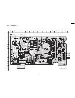
Page 53: ...14 2 Main P C B 53 SA HT640WPL ...
Page 60: ...SA HT640WPL 60 ...
Page 68: ...SA HT640WPL 68 ...
Page 70: ...70 SA HT640WPL ...
Page 80: ...SA HT640WPL 80 ...
Page 86: ...SA HT640WPL 86 ...
Page 88: ...SA HT640WPL 88 ...
Page 97: ...97 SA HT640WPL ...
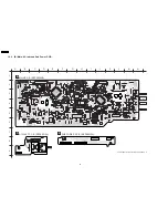
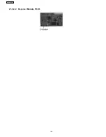
Page 104: ...21 3 4 2 Receiver Module P C B 104 SA HT640WPL ...
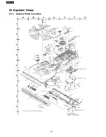
Page 106: ...23 Explode Views 23 1 Cabinet Parts Location 106 SA HT640WPL ...
Page 107: ...107 SA HT640WPL ...
Page 108: ...108 SA HT640WPL ...
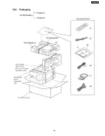
Page 109: ...23 2 Packaging 109 SA HT640WPL ...


