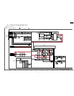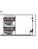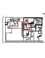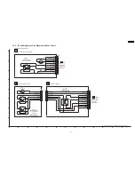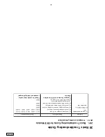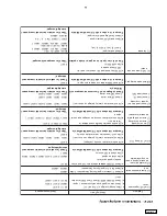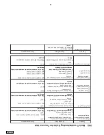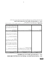
20.2. Basic
TroubleshootingGuide
forTraverse
Unit
*Compare the above w
ith OK condition
Module
Ch
ecking components
a) C
heck
LD
curr
en
t
Ch
eckin
g Points
8) Jitter out of specification
Prob
lems
b) Che
ck
OP
U (
cha
nge
to
othe
r uni
t a
nd
co
nfir
m)
*Check f
or solder short and/or component
damaged
IC
8051
Q8550,
Q8560,
Q8561,
Q8562
Q8550,
Q8551,
Q8552,
Q8560
*Check f
or solder short and/or component missing
/ damaged
*Check f
or solder short and/or component
damaged
Q8550,
Q8551,
Q8552,
Q8560,
Q8561,
Q8562
FP8201
IC
8251
IC
8251
Q8550,
Q8551,
Q8552,
Q8560,
Q8561,
Q8562
IC
8001
*Check f
or solder short and/or component missing
/ damaged
LB8301, R8321, R8322, LB8302, R8325, R8326
IC
8421
*Check f
or solder short and/or component missing
/ damaged
a) C
heck
la
se
r d
riv
e circ
uit
ry
(vo
lta
ge
s a
nd
cu
rre
nt)
- C
heck
CD
la
se
r d
riv
e
*C
om
pa
re
th
e ab
ov
e wit
h O
K co
nd
iti
on
M
odul
e
- C
heck
DV
D la
se
r d
riv
e
*Check voltages and LD current and
compare with OK Module
a) Che
ck
SD
RA
M a
ddre
ss
and da
ta
bus
sig
na
l
b) Che
ck
vide
o s
ign
als
c) C
heck
au
dio
DA
C ci
rc
uit
ry
b) C
heck
la
se
r d
riv
e circ
uit
ry
(vo
lta
ge
s
and
cu
rre
nt)
c) C
heck
LS
I co
nn
ectio
n t
o m
oto
r d
riv
e
cir
cui
try
*Compare the above with OK condition
Module
a) C
heck
con
nect
io
n f
ro
m B
ack
end
M od
ule
to
Traverse unit
b) C
heck
mo
to
r d
riv
er ci
rc
uit
ry
on
vo
lta
ges
and
co
ntro
l signals
*Compare the above with OK condition
Module
a) C
heck
mo
to
r d
riv
er ci
rc
uit
ry
(vo
lta
ge
s)
7) Block noise during
play
- Cannot
read CD
- Cannot
read DVD
6) Cannot read disc but
spindle is spinning
3) Disc not spinning
4) Trav
erse not mo
ving
5) Trav
erse and spindle
abnormal movement
2) No TO
C/Long
TO
C
Ch
ecking components
1) Distorted picture or
abnormal sound is heard
during initialisation
Prob
lems
Ch
eckin
g Points
a) Ch
eck SD
RA
M addresand data bus,
CLK and ot
her control signals waveform
IC
8051
95
SA-HT640W
PL
Summary of Contents for SA-HT640WPL
Page 4: ...23 2 Packaging 109 24 Replacement Parts List 110 24 1 Component Parts List 111 4 SA HT640WPL ...
Page 10: ...10 SA HT640WPL ...
Page 16: ...16 SA HT640WPL ...
Page 19: ...8 2 Detail Block Diagram Receiver module 19 SA HT640WPL ...
Page 31: ...31 SA HT640WPL ...
Page 37: ...10 1 Disassembly Flow Chart 37 SA HT640WPL ...
Page 38: ...10 2 Main Components and P C B Locations 38 SA HT640WPL ...
Page 46: ...Step 3 Push tray assembly to the direction of arrow shown 46 SA HT640WPL ...
Page 53: ...14 2 Main P C B 53 SA HT640WPL ...
Page 60: ...SA HT640WPL 60 ...
Page 68: ...SA HT640WPL 68 ...
Page 70: ...70 SA HT640WPL ...
Page 80: ...SA HT640WPL 80 ...
Page 86: ...SA HT640WPL 86 ...
Page 88: ...SA HT640WPL 88 ...
Page 97: ...97 SA HT640WPL ...
Page 104: ...21 3 4 2 Receiver Module P C B 104 SA HT640WPL ...
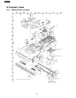
Page 106: ...23 Explode Views 23 1 Cabinet Parts Location 106 SA HT640WPL ...
Page 107: ...107 SA HT640WPL ...
Page 108: ...108 SA HT640WPL ...
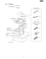
Page 109: ...23 2 Packaging 109 SA HT640WPL ...

