background image

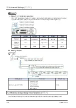
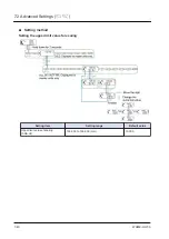
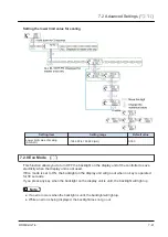
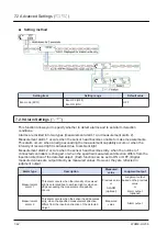
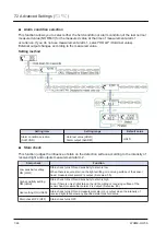
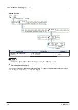
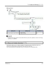
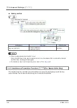
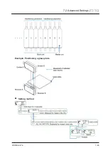
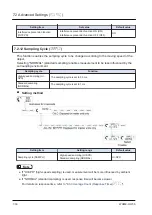
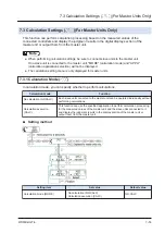
Setting method

Setting item

Setting range

Default value

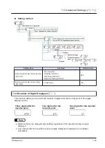
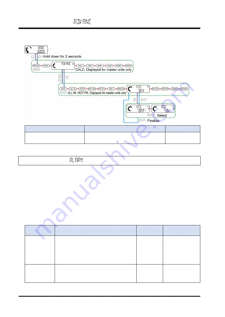
Eco mode (ECO)

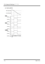
Eco OFF (OFF)
Eco ON (ON)

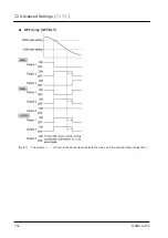
OFF

7.2.9 Alarm Settings (

)

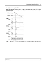
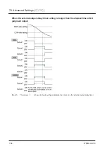
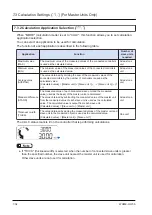
This function allows you to specify whether to detect alarms and to set alarm detection

conditions.
Alarms are divided into two types (measurement alarm 1 and measurement alarm 2).
Measurement alarm 1 occurs when the sensor head becomes unable to make measurements.

This alarm occurs when an edge exceeding the measurement capability occurs or when the

intensity of received light is saturated due to ambient light.
Measurement alarm 2 occurs when the sensor head becomes dirty, when the number of

connected controllers is changed, or when the specified measurement direction differs from the

insertion direction of the detected object. (Each function can be set to ON or OFF.) Digital

measured values are output directly as measured values. However, they are reflected in

judgment output.

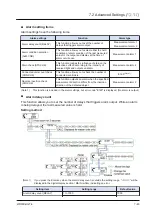
Alarm type

Description

Measured

value

Judgment output

Measurement

alarm 1

This alarm occurs when the intensity of received
light is saturated due to ambient light or when an
edge exceeding the measurement capability
occurs.

Previous value

or

ALARM

(optional)

Judgment output

based on the previous

value

or

alarm output

(optional)

Measurement

alarm 2

This alarm occurs when the sensor head becomes
dirty, when the specified measurement direction
differs from the insertion direction of the detected
object.

Measured

value

Alarm output

7.2 Advanced Settings (

)

7-42

WUME-HGT-6

Summary of Contents for HG-T Series

Page 1: ...Thru Beam Type Digital Displacement Sensor HG T series User s Manual WUME HGT 6 2020 11 panasonic net id pidsx global ...

Page 2: ... MEMO 2 WUME HGT 6 ...

Page 3: ...download from our website https panasonic net id pidsx global Unit name or purpose of use Manual name Manual code HG T Control Unit HG T User s Manual WUME HGTM HG T Configuration Tool HG T Configuration Tool User s Manual WUME HGTCT Please note 1 No part of this manual may be reproduced or reprinted in any form or by any means without prior written permission from Panasonic 2 The contents of this...

Page 4: ...to measurement startup the base screen displayed when the power is turned ON and basic operations Chapter 6 Setting up General Functions This chapter explains details and settings for general functions Chapter 7 Setting up Extended Functions This chapter explains details and settings for extended functions Chapter 8 Specifications and Dimensions This chapter explains the specifications and dimensi...

Page 5: ...g Connected Controllers 3 4 4 Installation and Connections 4 1 4 1 Mounting the Controller 4 2 4 1 1 Mounting on a DIN Rail 4 2 4 1 2 Removing from a DIN Rail 4 2 4 1 3 Controller Wiring Connection Diagrams 4 3 4 2 Attaching the Sensor Head 4 4 4 3 Connecting the Sensor Head Connection Cable 4 5 4 3 1 Connecting to the Sensor Head 4 5 4 3 2 Disconnecting from the Sensor Head 4 6 4 3 3 Connecting t...

Page 6: ... Loading Settings to from Banks 5 35 5 5 4 Key Lock 5 38 5 5 5 Sensitivity Settings 5 40 5 6 Self monitoring Function 5 47 5 6 1 Using the Self monitoring Function 5 47 5 6 2 Statuses and Measures 5 48 6 Setting up General Functions 6 1 6 1 Flow of Measurement Data 6 2 6 2 Setting Operation List 6 4 6 3 Detection Settings 6 9 6 3 1 Operation Mode 6 9 6 3 2 Measurement Direction 6 10 6 3 3 Average ...

Page 7: ...2 Calculation Application Selection 7 54 7 4 Copy Settings 7 59 7 4 1 Copy Individual Selection For Master Units Only 7 59 7 4 2 Copy Batch Selection For Master Units Only 7 62 7 4 3 Copy Execution For Master Units Only 7 62 7 4 4 Copy Lock For Slave Units Only 7 63 7 5 Bank Settings 7 65 7 5 1 Bank Save Selection 7 65 7 6 Calibration Settings 7 67 7 6 1 Calibration Selection 7 67 7 7 Tab Cancella...

Page 8: ...on 9 2 9 1 1 Maintenance Precautions 9 2 9 1 2 Main Inspection Items 9 2 10 Troubleshooting 10 1 10 1 Troubleshooting 10 2 10 2 Error Messages 10 5 Appendix Appendix App 1 Menu Structure General Function Display App 2 Menu Structure Extended Function Display App 4 viii WUME HGT 6 ...

Page 9: ...afety Precautions Always observe 1 2 1 2 Handling Precautions 1 3 1 3 Laser Safety Standards 1 5 1 3 1 IEC JIS GB 1 5 1 3 2 FDA 1 6 1 4 Terminology 1 9 1 5 Contents of Package 1 10 1 6 Product Version and Functions 1 12 WUME HGT 6 1 1 ...

Page 10: ...that affect human lives or property Do not look at or touch direct laser beams or other reflections of light as doing so is dangerous For the controller DC power supply only use a power supply that is isolated by means of an isolation transformer or otherwise There is a risk of short circuiting and damage to the controller or power supply if a transformer such as an autotransformer is used There i...

Page 11: ...er supply is connected to an actual ground Do not use during the initial transient time after the power supply is switched ON To ensure performance use the product at least 30 minutes warm up time after the power is turned ON Wiring Make sure that the power is OFF before performing wiring or connection work for the controller Note that there is a risk of damage or burning if the load is short circ...

Page 12: ...rs due to sudden temperature change Avoid dust dirt and steam Avoid using the product in atmospheres that contain corrosive or other harmful gases Ensure that the product does not come into contact with organic solvents such as thinner Ensure that the product does not come into contact with strong acid or alkaline Ensure that the product does not come into contact with oil or grease This product c...

Page 13: ...laser beams is safe when the operating state of the product is rightly predictable but direct intrabeam viewing by optical means can be dangerous Class 2 This class of laser beams is visible light and low output Normally eyes are protected by aversion reaction such as blinking Class 2M This class of laser beams is visible light and low output Normally eyes are protected by aversion reaction such a...

Page 14: ...is product complies with the FDA regulations 21 CFR 1040 10 and 1040 11 in accordance with FDA Laser Notice No 50 Class 1 laser product FDA regulations Requirements Class Note 1 Ⅰ Ⅱa Ⅱ Ⅲa Ⅲb Ⅳ Performance for all laser products Protective housings 1040 10 f 1 R Note 2 R Note 2 R Note 2 R Note 2 R Note 2 R Note 2 Safety interlock 1040 10 f 2 R Note 3 Note 4 R Note 3 Note 4 R Note 3 Note 4 R Note 3 ...

Page 15: ...nts as for other products of the class NP Not permitted D Depends on the internal radiation level Note 1 Based on the maximum level of exposure to radiation during operation Note 2 Required wherever and whenever if exposure to laser radiation exceeding the limit of Class 1 is not necessary to fulfill the functions of the product Note 3 Required for protective housings that are opened during operat...

Page 16: ... products and light show for demonstration of Class IIIb or IV Note 12 DANGER logo Note 13 Required since August 20 1986 Recognition identification label Label position Emitter Common to HG T1010 and HG T1110 1 3 Laser Safety Standards 1 8 WUME HGT 6 ...

Page 17: ...le that is used to connect a sensor head and controller Side view attachment An attachment that is used to refract laser beams from the sensor head at 90 degrees End plate A plate that is used to secure both ends of controllers to prevent the connectors from coming off and causing a communication failure when controllers are connected Communication unit An interface unit that enables measurement d...

Page 18: ...performance PNP output type Controller 1 pc Instruction manual English Japanese Chinese Korean 1 pc each General Information for Safety Compliance and Instructions 23 languages 1 pc HG TC113 Slave unit of wire saving type Controller 1 pc Instruction manual English Japanese Chinese Korean 1 pc each General Information for Safety Compliance and Instructions 23 languages 1 pc Sensor head HG T1010 Mea...

Page 19: ... TSV10 Side view attachment Attachment 1 pc Note 1 M2 screw with washer length 4 mm 2 pcs CN HT C2 Cable length 2 m CN HT C5 Cable length 5 m CN HT C10 Cable length 10 m CN HT C20 Cable length 20 m Connection cable 1 pc Note 1 HG TSV10 is sold by one unit Two units are required for a pair of emitter and receiver End plate MS DIN E End plate Plate Set of 2 pcs Instruction manual 1 5 Contents of Pac...

Page 20: ...ng 7 2 1 Hold Settings Hold state output External output 7 2 4 External Outputs Measured value reversal selection function Measured value reversal 7 2 13 Reverse of Measured Value The controllers and sensor heads manufactured in October 2020 or earlier do not support the above functions Please note this point How to check manufacturing year and month Check the manufacturing lot No shown in the fol...

Page 21: ...ystem Configuration 2 1 System Configuration 2 2 2 2 Description of Parts 2 3 2 2 1 Controller 2 3 2 2 2 Sensor head 2 5 2 2 3 Sensor Head Connection Cable 2 6 2 2 4 Side View Attachment 2 6 WUME HGT 6 2 1 ...

Page 22: ...necting a slave unit or communication unit to from the master unit If you connect or disconnect a unit with the power ON the controller may become damaged Insert the male connector all the way into the female connector If the connectors are not completely connected the controller may become damaged To connect units always mount them on a DIN rail To do so mount end plates MS DIN E optional so as t...

Page 23: ...11 P Slave unit of high performance PNP output type HG TC113 Slave unit of wire saving type Name Function 1 Female connector For connection to a slave unit Remove the connector cover before connecting to a slave unit 2 Sensor head connection cable connector Connects the sensor head connection cable 3 Male connector for slave unit only For connection to a master unit or slave unit 2 2 Description o...

Page 24: ...ion MAIN White Shows the measured value judgment value and setting 7 Guide mark arrow keys White Lights up when each key LEFT RIGHT UP DOWN is enabled during each setting operation 8 Guide mark Enter White Lights up when the ENTER key is enabled during each setting operation 9 LEFT key Used to change setting items and settings when configuring settings and to move through set value digits 10 UP ke...

Page 25: ...n the preset function is used 19 Preset key Used to set and cancel the preset function 2 2 2 Sensor head HG T1010 Emitter Receiver HG T1110 Emitter Receiver Name Function 1 Laser radiation indicator Green Lights up when laser beams are emitted 2 Light emitting surface The surface that emits laser beams 3 Light receiving surface The surface that receives laser beams 2 2 Description of Parts WUME HG...

Page 26: ...onnector Connects the sensor head connection cable 8 Female thread for mounting side view attachment Connects the side view attachment and sensor head using an M2 screw with washer length 4 mm Note 1 The HG T1110 is not equipped with the beam axis adjustment indicators TOP BOTTOM part 2 2 3 Sensor Head Connection Cable CN HT C2 Cable length 2 m CN HT C5 Cable length 5 m CN HT C10 Cable length 10 m...

Page 27: ...ts the side view attachment on the light emitting and receiving surfaces of the sensor head 2 Sensor head mounting hole Connects the side view attachment and sensor head using an M2 screw with washer length 4 mm 2 2 Description of Parts WUME HGT 6 2 7 ...

Page 28: ... MEMO 2 8 WUME HGT 6 ...

Page 29: ...3 Overview of HG T Series 3 1 Principle of Measurement 3 2 3 2 Role of Controllers 3 3 3 3 Using Connected Controllers 3 4 WUME HGT 6 3 1 ...

Page 30: ...ry section that receives laser beams and the dark section light interception section that is the shade of the measured object are projected on to the CMOS The difference in the amount of received light between each pixel of the CMOS is used to detect position information about the border between the light entry section and the light interception section and measure the object The edge position of ...

Page 31: ... the controller and calculations performed The results of the calculations are displayed as judgment values Output judgment is based on judgment values The controller is equipped with three outputs OUT 1 OUT 2 and OUT 3 and with indicators that show the respective results of the three outputs 3 2 Role of Controllers WUME HGT 6 3 3 ...

Page 32: ...he connected controllers and output the calculation results from the master unit Example Thickness width measurement The measured values that the master unit and the slave unit obtain for the measured object are added This enables the width of the measured object to be measured Other functions that are valid when controllers are connected include the interference prevention function and calculatio...

Page 33: ...necting the Sensor Head Connection Cable 4 5 4 3 1 Connecting to the Sensor Head 4 5 4 3 2 Disconnecting from the Sensor Head 4 6 4 3 3 Connecting to the Controller 4 6 4 3 4 Disconnecting from the Controller 4 7 4 3 5 Connecting and Disconnecting to from Controller Connector 4 7 4 4 Connecting Controllers 4 10 4 4 1 How to Connect 4 11 4 4 2 How to Remove 4 13 4 5 Mounting the Side View Attachmen...

Page 34: ... controller on a DIN rail 2 While pushing the rear of the mounting part forward insert the front of the mounting part into the DIN rail 4 1 2 Removing from a DIN Rail 1 Grasp the controller and push it forward 2 Lift up the front part of the controller to remove it 4 1 Mounting the Controller 4 2 WUME HGT 6 ...

Page 35: ...G TC111 P Slave unit Note 1 Use a shielded cable to extend the analog output line The HG TC111 and HG TC111 P cables do not have V or 0V Power is supplied from the connector of the master unit The HG TC113 does not have V 0V or any I O The connector on the slave unit is used to connect to the master unit 4 1 Mounting the Controller WUME HGT 6 4 3 ...

Page 36: ...or similar material moistened with absolute alcohol A serial number is marked on each opposite surface of the light emitting and receiving surfaces of the sensor head Use a pair of emitter and receiver that have the same serial number Use M3 screws to be prepared by the customer to mount the sensor head Tighten the screws to a torque of 0 5 N m Mounting hole dimensions HG T1010 HG T1110 Emitter Re...

Page 37: ... break if excessive stress is applied to the cable After inserting the connectors verify that both are attached firmly If loose a connector may fall out and cause an error The sensor head connection cable branches into two cables The cables are identical and can be connected to either the emitter or receiver 1 Insert the sensor head connecting cable to the sensor head connection cable connector of...

Page 38: ...g always make sure that the fastening ring has been completely loosened before pulling out the cable Risk of damage if you pull the cable with excessive force 15 N or more with the fastening ring tightened 4 3 3 Connecting to the Controller Insert the controller connector on the sensor head connection cable into the connector for the sensor head connection cable on the controller 4 3 Connecting th...

Page 39: ... the lever toward you to disconnect the cable If you attempt to disconnect the cable by pulling it without pressing the lock release lever cable wire breakage and connector damage may occur 4 3 5 Connecting and Disconnecting to from Controller Connector The cable on the controller connector side can be shortened Use the following procedures to disconnect and connect the cable from to the controlle...

Page 40: ...h wire Connection procedure 1 Align the tip of the wire with the STRIP GAUGE mark on the side of the connector strip the cable so that the core wire length is 7 to 8 mm and twist the core wires several times 2 Using a flathead screwdriver with a tip width of 2 mm or less press down the lever white on the operation unit until the lever locks 4 3 Connecting the Sensor Head Connection Cable 4 8 WUME ...

Page 41: ...ds x2 4 Insert the tip of the flathead screwdriver into the release hole so that it contacts the bottom of the lever white and move the tip of the flathead screwdriver up The lever white will make a click sound when it returns to its original position and the wire will be locked 5 Pull on the wire gently to ensure that it does not come out 6 Slide the protective cover in the direction of the arrow...

Page 42: ...cting slave units to a master unit connect only NPN output types or only PNP output types Dissimilar output types cannot be connected together An HG SC series controller manufactured in January 2019 or earlier cannot be used together with an HG TC series controller To use these controllers together use an HG SC series controller manufactured in February 2019 or later To connect units the units mus...

Page 43: ...as the master unit Calculation is not performed when the slave unit series is different from the master unit series CALC does not appear in the display of a slave unit of a different series 2 Input all The master unit only performs input all when the slave units are the same series A slave unit of a different series from the master unit does not perform input even when the external input settings ...

Page 44: ... all connector covers except for the cover on the end slave unit 4 Slide each slave unit and connect the female and male connectors 5 Attach end plates MS DIN E optional with the flat side facing in so as to enclose the connected units at the ends 4 4 Connecting Controllers 4 12 WUME HGT 6 ...

Page 45: ... or less Take care that this product might become damaged if the screws are tightened to a torque exceeding 0 3 N m 4 4 2 How to Remove 1 Loosen the screws on the end plates 2 Remove the end plates 3 Slide and remove the controllers one at a time 4 4 Connecting Controllers WUME HGT 6 4 13 ...

Page 46: ... on sensor head HG T1010 makes various installations possible Note 1 When mounting a side view attachment on the sensor head use the M2 screws with a washer length 4 mm provided Tighten the screws to a torque of 0 088 N m or less Example of HG TSV10 mounted on both sides Note 2 Notes 1 Side view attachments cannot be mounted on sensor head HG T1110 measurement width 10 mm slim type 2 HG TSV10 is s...

Page 47: ...tion Mode 5 22 5 4 2 Edge Detection Mode 5 23 5 4 3 Outer diameter Width Detection Mode 5 24 5 4 4 Inner Diameter Gap Detection Mode 5 25 5 4 5 Central Position Detection Mode 5 25 5 4 6 User Assigned Edge Detection Mode 5 27 5 5 Settings on the Base Screen Using Shortcut Keys 5 30 5 5 1 Display Switching Mode 5 30 5 5 2 Preset 5 33 5 5 3 Saving and Loading Settings to from Banks 5 35 5 5 4 Key Lo...

Page 48: ...5 1 Using the Base Screen 5 1 1 Functions of Operation Pad and Display Unit Functions of the operation pad Controller 5 1 Using the Base Screen 5 2 WUME HGT 6 ...

Page 49: ...he key is disabled During setting Lit when the Enter key must be pressed Green Digital display section SUB During measurement Shows the measured value Example Base screen During setting Shows the selected setting item Example Screen when HIGH set value is set White Digital display section MAIN During measurement Shows the judgment value that was used for judgment 5 1 Using the Base Screen WUME HGT...

Page 50: ...ured object by incrementing or decrementing the meter count Example When the measured value is below LOW set value Orange Example When the measured value is GO Green Example When the measured value is above HIGH set value Orange GO is a value within the judgment range set with the HIGH set value and LOW set value During setting Shows setting item positioner navigation blinking 5 1 Using the Base S...

Page 51: ...creen When there is no measured object between the emitter and receiver during measurement mode the display of the controller display unit is as shown below State of sensor head State of controller display unit The state in which this screen is displayed is called indeterminate state 5 1 Using the Base Screen WUME HGT 6 5 5 ...

Page 52: ...eams are output from the sensor head emitter 4 Checking the beam axis Check whether the beam axis of the sensor head is aligned 5 3 1 Checking the Beam Axis 5 Adjust the beam axis if the beam axis is not aligned Readjust the beam axis according to the beam axis adjustment method 5 3 2 Adjusting the Beam Axis 6 Registering the reference waveform Register the reference waveform according to the refe...

Page 53: ...mally Open Default 6 4 10 Output Operation 8 Start measurement Measurement is started Check the value measured by the controller and the judgment value 5 1 1 Functions of Operation Pad and Display Unit 9 Fine adjustment To change the GO range change the HIGH set value and LOW set value to any desired values 6 4 1 HIGH Set Value 6 4 2 LOW Set Value 5 2 Flow of Operations up to Measurement Startup W...

Page 54: ...m axis Beam axis adjustment mode Hold down the key and key simultaneously on the operation unit of the controller for two seconds To check the beam axis using the controller If the beam axis is aligned all LED segments of the circle meter on the left side of the display unit light up in green At the same time the bar mark in the middle of the display section MAIN lights up in white The guide mark ...

Page 55: ...ontroller 5 3 2 Adjusting the Beam Axis Invoke beam axis adjustment mode and check the state of the beam axis by using the display unit of the controller or the beam axis adjustment indicators on the sensor head receiver except for HG T1110 Checking the beam axis on the display unit of the controller Example The emitter is too low with respect to the receiver First when adjusting the beam axis sel...

Page 56: ...s shifted toward the TOP side the light emitting side has shifted toward the BOTTOM side Note 1 Unlit The light receiving side has shifted toward the BOTTOM side the light emitting side has shifted toward the TOP side All segments unlit Unlit The beam axis is completely out of alignment Laser emission stop input turns ON during beam axis adjustment The measured object intercepts the entire beam ax...

Page 57: ...tment indicators on the sensor head receiver Except for HG T1110 Depending on the state of the beam axis of the sensor head the displays of the beam axis adjustment indicators TOP and BOTTOM parts on the sensor head receiver change as shown below State of beam axis adjustment indicator TOP BOTTOM part State of beam axis The light receiving side has shifted toward the TOP side the light emitting si...

Page 58: ...is covered with a transparent body Objects intercepting light or stains adhering substances exist inside the measurement area 1 Holding down the key and key for two seconds invokes beam axis adjustment mode The number of lit increments in the circle meter increases while the keys are held down 2 Press the or key to select either receiver base or emitter base for beam axis adjustment The sensor hea...

Page 59: ... display unit of the controller refer to Checking the beam axis on the display unit of the controller For the display of the beam axis adjustment indicators on the sensor head receiver refer to Checking the beam axis using the beam axis adjustment indicators on the sensor head receiver Except for HG T1110 4 Move the receiver of the sensor head vertically and laterally while checking the display un...

Page 60: ...rk Enter will light up in white Sensor head 6 If you confirm that the beam axis has been aligned proceed to 5 3 3 Reference Waveform Registration To return to measurement mode press the key 5 3 3 Reference Waveform Registration By registering the reference waveform you can register waveforms in a normal state Registering normal waveforms helps to improve measurement accuracy and discover any abnor...

Page 61: ...ect so that reflected light does not hit the emitter or receiver After adjusting the angle always adjust the beam axis 1 Invoke beam axis adjustment mode and check that the beam axis is aligned using the circle meter and guide mark Enter on the display unit of the controller or the beam axis adjustment indicators at TOP and BOTTOM parts on the sensor head receiver Controller display unit Sensor he...

Page 62: ...d to be out of range on LOW or HIGH side Term Description GO Refers to the judgment range between the HIGH set value and LOW set value Settings Teaching type Setting method 1 point teaching Default You can use a master workpiece to set upper and lower limit values Use this method when you want to set judgment values for the workpiece as tolerance 2 point teaching You can use two workpieces to set ...

Page 63: ...as upper and lower limits Note 1 Upper and lower limit values are regarded as HIGH and LOW set values respectively The default setting for the tolerance is 0 100 0 100 When 1 point teaching is selected 1 Hold down the key for 2 seconds The number of lit increments in the circle meter increases SET1 appears in the digital display section SUB green and the digital display section MAIN white blinks 2...

Page 64: ...play section MAIN restore the controller to its normal state and then execute teaching again If teaching is performed when one of the messages in the table below appears in the digital display section during measurement teaching will not take place correctly and an error will be displayed In this case restore the controller to its normal state and then execute teaching Digital display section Desc...

Page 65: ...AIN white blinks 3 Measure the first workpiece and then press key 4 SET 2 appears in the digital display section SUB green Measure the second workpiece and then press key When teaching is completed GOOD appears in the digital display section MAIN white and the HIGH set value and LOW set value are applied Then the display will automatically return to the base screen 5 3 Explanation of Basic Operati...

Page 66: ...Step 4 When 3 point teaching is selected 1 Hold down the key for 2 seconds The number of lit increments in the circle meter increases 2 SET 1 appears in the digital display section SUB green and the digital display section MAIN white blinks 3 Measure the HIGH side defective workpiece and press the key 5 3 Explanation of Basic Operation 5 20 WUME HGT 6 ...

Page 67: ...nd the HIGH set value and LOW set value are applied Then the display will automatically return to the base screen Regardless of the order of Step 3 Step 4 and Step 5 the workpiece judgment values are sorted in order from the highest to the lowest value The intermediate value between the highest value and the median value is set as the HIGH set value and the intermediate value between the lowest va...

Page 68: ...e measured object enters the measurement area of the sensor head TOP or BOTTOM side The distance from the edge of the side where the measured object enters the measurement area to the edge of the measured object is measured When the measured object enters the measurement area from the TOP side On the basis of the TOP side the distance from the TOP side edge to the edge of the measured object is de...

Page 69: ... object enters the measurement area from the TOP side LOW set value 2 0 mm is used When the measured object enters the measurement area from the BOTTOM side LOW set value 2 0 mm is switched to HIGH set value 8 5 mm When the measured object enters the measurement area from the BOTTOM side HIGH set value 7 0 mm is used When the measured object enters the measurement area from the TOP side HIGH set v...

Page 70: ...d as the BOTTOM side The measured object moves in the direction opposite to the one when the direction in which the measured object enters the measurement area is specified as the TOP side Full light entry state is displayed as For details on how to set the measurement direction refer to 6 3 2 Measurement Direction 5 4 3 Outer diameter Width Detection Mode This mode measures the outer diameter or ...

Page 71: ...entry that is nearer to the TOP side to the next edge switching from light entry to light interception is detected as the measured value There is no need to set the measurement direction The following states are judged to be indeterminate states and displayed as Full light interception state Full light entry state 5 4 5 Central Position Detection Mode When an object such as a pin is measured this ...

Page 72: ...itches from light interception to light entry Measured value A TOP side edge When the measurement direction is specified as the BOTTOM side On the basis of the BOTTOM side the central value A between the first edge B switching from light entry to light interception and the last edge C switching from light interception to light entry is calculated The distance from the BOTTOM side edge to the centr...

Page 73: ...es the distance between two edges that are optionally specified Assigned edges are numbered from 1 to 10 in the order of appearance from the TOP It is possible to specify TOP or BOTTOM to one of the assigned edges Be careful that an alarm 1 will be detected if 11 or more edges are recognized A change either from light interception to light entry or from light entry to light interception is recogni...

Page 74: ...OP BOTTOM position and the edge position example between the TOP position and edge No 1 Note 1 Perform beam axis adjustment only when there is no obstacle Full light entry state is displayed as Setting method 5 4 Operation Mode 5 28 WUME HGT 6 ...

Page 75: ...Setting item Setting range Default value edge1 EDGE1 TOP 1 10 BOTTOM 1 edge2 EDGE2 TOP 1 10 BOTTOM 2 5 4 Operation Mode WUME HGT 6 5 29 ...

Page 76: ...Description Factory default state 1 Normal measured value Shows the normal measured value When using the hold function you can check internal measured values that are not held Default state 2 Calculated value Note 1 Shows the calculated value When using the calculation function and hold function you can check calculation results that are not held 3 Label You can view and set any values or characte...

Page 77: ...n function CALC appears on the slave units but not on the master unit When the calculation function is not used this does not appear on either the master unit or the slave units CALC does not appear on a master unit that is not connected to slave units Normal Value is the normal measured value to which the preset measurement direction and calibration functions are reflected Head Value is the measu...

Page 78: ...if you press the key with LABEL selected you will move to the label setting screen Label settings 1 If you press the key with LABEL selected in display switching mode you will move to the label setting screen 5 5 Settings on the Base Screen Using Shortcut Keys 5 32 WUME HGT 6 ...

Page 79: ...oint adjustment and shift to any preset value You can perform reference zero point adjustment when the sensor head has been replaced or when the workpiece has been changed and set the dimensions of the master workpiece or the like as preset values for use as master values reference values Presets 1 Perform master workpiece measurement 5 5 Settings on the Base Screen Using Shortcut Keys WUME HGT 6 ...

Page 80: ...power is turned OFF The internal memory can be used approximately one million times If one of the messages in the table below appears in the digital display section the preset function has not been executed correctly and an error has occurred In this case restore the controller to its normal state and then execute the preset function Digital display section Description MAIN White SUB Green Display...

Page 81: ...her settings to from a specified bank 1 to 3 You can use the bank function to save settings for an object to be measured in a bank beforehand and easily load the settings when needed Types of setting items saved to and loaded from banks Setting item Factory default state All setting items HIGH set value LOW set value Default state 5 5 Settings on the Base Screen Using Shortcut Keys WUME HGT 6 5 35...

Page 82: ...wer is turned OFF The internal memory can be used approximately one million times Saving and loading to from banks by key operation 1 Hold down the key for 2 seconds The number of lit increments in the circle meter increases 2 SAVE appears in the digital display section SUB green 3 Press the key to switch between SAVE and LOAD 4 Press the key BANK1 appears in the digital display section SUB green ...

Page 83: ...witch between YES and NO 8 Press the key If you selected SAVE in Step 3 the current settings are saved to the bank If you selected LOAD in Step 3 the settings saved in the bank are loaded 9 Press the key twice to return to the base screen 5 5 Settings on the Base Screen Using Shortcut Keys WUME HGT 6 5 37 ...

Page 84: ...hown below Bank No to load from Bank A input Bank B input Bank 1 ON OFF Bank 2 OFF ON Bank 3 ON ON Settings cannot be saved to banks by external input 5 5 4 Key Lock Overview You can lock the operation keys to prevent accidental key operation during measurement While key lock is activated all key operations other than key lock release cannot be performed Key lock setting 1 Hold down the key and ke...

Page 85: ...hite Functions that use external input are enabled You can configure settings to activate key lock automatically when key operation is not performed for 5 minutes or more Key lock release 1 While key lock is enabled hold down the key and key simultaneously for 2 seconds OFF appears in the digital display section MAIN white and lock is released Note 1 Even when auto key lock is enabled you can use ...

Page 86: ...ead receiver is in a light entry state or light interception state according to the intensity of light received by the receiver If the intensity of received light that is registered as the reference waveform is regarded as 100 and the intensity of received light falls below a judgment level of 25 default value the receiver will be judged to be in a light interception state and the edge position wi...

Page 87: ... display section MAIN white 4 Press the key to switch between DEFALT default and USER user settings Sensitivity setting Function Default DEFALT Sets to the default state User settings USER Allows you to specify any desired judgment level value and judgment filter value 5 Select USER user settings and press the key JDG LVL judgment level appears in the digital display section SUB green and 25 defau...

Page 88: ...judgment filter appears in the digital display section SUB green and 9 default appears in the digital display section MAIN white To return to the base screen halfway during setting hold down the key for 2 seconds Setting method Setting item Setting range Default value Judgment level JDG LVL 10 to 90 25 5 5 Settings on the Base Screen Using Shortcut Keys 5 42 WUME HGT 6 ...

Page 89: ...judged to be in a light interception state and the edge position measured value is calculated When dirt adheres to the emitter or receiver measurement can be continued unless at least three consecutive pixels appear in the light interception part If the filter value is too large small objects cannot be measured For judgment filter 3 1 Hold down the key and key simultaneously for 2 seconds The numb...

Page 90: ...DEFALT default and USER user settings Sensitivity setting Function Default DEFALT Sets to the default state User settings USER Allows you to specify any desired judgment level value and judgment filter value 5 Select USER user settings and press the key twice JDG FIL judgment filter appears in the digital display section SUB green and 9 default appears in the digital display section MAIN white 5 5...

Page 91: ...After setting a judgment filter press the key FINISH blinks in the digital display section MAIN white and then the display returns to the base screen To return to the base screen halfway during setting hold down the key for 2 seconds Setting method 5 5 Settings on the Base Screen Using Shortcut Keys WUME HGT 6 5 45 ...

Page 92: ...Setting item Setting range Default value Judgment filter JDG FIL 3 to 50 9 5 5 Settings on the Base Screen Using Shortcut Keys 5 46 WUME HGT 6 ...

Page 93: ...ost device The HG T series sensors incorporate the self monitoring function 5 6 1 Using the Self monitoring Function By combining the control system connected to PLC or PC via a network this product and the specified communication unit you can easily check the sensor status normal notification caution or fault The sensor itself judges even the causes of cautions and errors making cause investigati...

Page 94: ...ncompatible Status check P 10 5 E230 Connected unit count check error Status check P 10 5 E160 For master units only NPN PNP output type mixture error Status check P 10 5 E100 For master units only Calculated unit count error Status check P 10 5 E110 For master units only Copy execution error Slave unit problem Status check P 10 5 E170 For master units only Detection capability limit obtained edge...

Page 95: ...r head memory function damaged Sensor head replacement P 10 5 E630 For receivers only E640 For emitters only Output section short circuit error Status check Replacement P 10 5 E700 Detection circuit damaged Sensor head replacement P 10 5 E240 System error Controller replacement P 10 6 E900 E910 E911 E912 E920 Note 1 Error codes and measurement alarms are displayed on HG TC controllers Note 2 If Al...

Page 96: ... MEMO 5 50 WUME HGT 6 ...

Page 97: ...1 6 4 Basic Settings 6 14 6 4 1 HIGH Set Value 6 14 6 4 2 LOW Set Value 6 15 6 4 3 Hysteresis 6 17 6 4 4 Teaching Types 6 20 6 4 5 Tolerance 6 21 6 4 6 Preset Value 6 22 6 4 7 Preset Data Selection 6 23 6 4 8 Preset Save 6 24 6 4 9 Reference Waveform Save 6 25 6 4 10 Output Operation 6 26 6 4 11 Analog Output Selection 6 27 6 4 12 Menu Display Settings 6 28 6 5 Initialization 6 30 6 6 Maintenance ...

Page 98: ...n the following flowchart Example When one master unit and two slave units are connected and calculation application selection THICK thickness width measurement and independent measurement are used at the same time When the master unit and slave unit 1 perform calculations and slave unit 2 performs independent measurement Note 1 When calculation mode is selected the number of slave units performin...

Page 99: ... Note 2 Displayed only during calculation 6 1 Flow of Measurement Data WUME HGT 6 6 3 ...

Page 100: ...ings P 6 14 3 Initialization RESET This function allows you to return all controller settings other than calibration settings to the factory default settings P 6 30 4 Maintenance MAINTE This function displays the cumulative operating periods for the controller and sensor head P 6 31 Pressing the key in each setting mode allows you to enter a function selection item You can extend function selectio...

Page 101: ...dgment value JUDGE V is finalized and a judgment is output The response time differs depending on whether the sampling cycle is high speed sampling or standard sampling Default 32 P 6 11 The key operation for the key for returning to the setting mode selection screen also applies to the key Function selection Basic settings No Item Display screen Function Refere nce page Initial screen 2 Basic set...

Page 102: ...22 2 g Preset data selection PR OBJ This function allows you to select target data NORM V or JUDGE V to be preset Default NORM V P 6 23 2 h Preset save PR SAVE Setting preset save to ON allows you to write information preset with external input to the EEPROM of the controller Even if the power is turned OFF the preset ON OFF state and offset value remain stored Default OFF P 6 24 2 i Reference wav...

Page 103: ...ws you to return all controller settings other than calibration settings to the factory default settings The key operation for the key for returning to the setting mode selection screen also applies to the key Maintenance No Item Display screen Function Refere nce page Initial screen 4 Maintenance 4 a Cumulative operating period RUN TIM This function displays the cumulative operating period for th...

Page 104: ...lative head operating period HD TIME This function displays the cumulative operating period for the sensor head The key operation for the key for returning to the setting mode selection screen also applies to the key 6 2 Setting Operation List 6 8 WUME HGT 6 ...

Page 105: ...TOP or BOTTOM side this mode measures the distance from the TOP or BOTTOM side of the measurement area to the edge of the measured object Required Outer diameter width detection mode OUT WD This mode measures the outer diameter or width of the measured object Not required Inner diameter gap detection mode IN GAP This mode measures the inner diameter or gap of the measured object Not required Centr...

Page 106: ... object to the TOP or BOTTOM side Measurement direction Function TOP TOP When the measured object is inserted from the TOP side BOTTOM BOTTOM When the measured object is inserted from the BOTTOM side When set to TOP When set to BOTTOM When the operation mode OP MODE is set to auto edge detection mode AT EDGE outer diameter width detection mode OUT WD inner diameter gap detection mode IN GAP or use...

Page 107: ... until a judgment value JUDGE V is finalized and a judgment is output The response time differs depending on whether the sampling cycle is high speed sampling or standard sampling Sampling cycle Standard sampling NORMAL Average count number of times Sampling cycle ms Response time ms Update cycle ms 1 1 2 1 2 1 3 1 4 1 5 1 8 1 9 1 16 1 17 1 32 1 33 1 64 1 65 1 128 1 129 2 256 1 257 4 512 1 513 8 1...

Page 108: ... time ms Update cycle ms 1 0 5 1 5 0 5 2 0 5 2 0 5 4 0 5 3 0 5 8 0 5 5 0 5 16 0 5 9 0 5 32 0 5 17 0 5 64 0 5 33 0 5 128 0 5 65 1 256 0 5 129 2 512 0 5 257 4 1 024 0 5 513 8 When the average count is set to 8 Sampling cycle Standard sampling NORMAL Update cycle 6 3 Detection Settings 6 12 WUME HGT 6 ...

Page 109: ... the average count is reached after reset input turns ON For details on sampling cycles refer to 7 2 12 Sampling Cycle If MODE calculation mode is set to CALC calculate approximately 3 ms will be added to the response time for judgment output For details on calculation mode refer to 7 3 1 Calculation Mode Setting method Setting item Set value Default value Average count response time SPEED 1 2 4 8...

Page 110: ... value JUDGE V exceeds the HIGH set value the judgment is output as HIGH Be sure to set a HIGH set value that is greater than the LOW set value The HIGH set value can be always displayed in the digital display section SUB green For details refer to 5 5 1 Display Switching Mode By teaching you can set HIGH and LOW set values For details refer to 5 3 4 Teaching Setting method Setting item Setting ra...

Page 111: ...on MAIN white 2 Press the key to change the digit position Press the key to increase or decrease the numerical value 3 Press the key to finalize the setting If you take no action for 5 seconds the screen will automatically return to the base screen and the setting will be finalized 6 4 2 LOW Set Value This function allows you to set the LOW set value lower limit value to any desired value If the j...

Page 112: ...efer to 5 5 1 Display Switching Mode By teaching you can set HIGH and LOW set values For details refer to 5 3 4 Teaching Setting method Setting item Setting range Default value LOW set value LO SET 199 999 to 199 999 mm 1 000 In addition to this method you can also set a LOW set value directly from the base screen during measurement 6 4 Basic Settings 6 16 WUME HGT 6 ...

Page 113: ...seconds the screen will automatically return to the base screen and the setting will be finalized 6 4 3 Hysteresis If the measured object vibrates in the vicinity of the HIGH LOW set value the judgment value may fluctuate resulting in unstable operations Increasing the value of hysteresis makes operations stable If hysteresis is 0 The judgment value JUDGE V fluctuates in the vicinity of the HIGH s...

Page 114: ...or LOW set value judgment output will be stable In the following timing chart external output is set to 3VAL and output operation is set to N O For details on external output refer to 7 2 4 External Outputs For details on output operation refer to 6 4 10 Output Operation 6 4 Basic Settings 6 18 WUME HGT 6 ...

Page 115: ... value and LOW set value the judgment is not output as GO Even if hysteresis is set be sure to set a HIGH set value that is greater than the LOW set value If the LOW set value is set to a value that is equal to or greater than the HIGH set value the judgment is not output as GO Setting method Setting item Setting range Default value Hysteresis HYSTER 0 to 199 999 mm 0 003 6 4 Basic Settings WUME H...

Page 116: ...lly set upper and lower limit values Use this method when you want to judge workpieces within an upper limit and lower limit range 3 point teaching You can use a good workpiece a HIGH side defective workpiece and a LOW side defective workpiece to automatically set upper and lower limit values Use this method when you want to judge workpieces within a range that takes the intermediate values betwee...

Page 117: ...gment value JUDGE V of the master workpiece plus the tolerance can be set as the HIGH set value and the judgment value of the master workpiece minus the tolerance can be set as the LOW set value Note 1 When the tolerance is set to 1 000 Settings of tolerance are valid only when 1 point teaching is set For details on how to perform 1 point teaching refer to 5 3 4 Teaching 6 4 Basic Settings WUME HG...

Page 118: ...ues for use as master values reference values Setting preset to OFF shifts the measured value Setting preset to ON with the preset value set to 0 default value performs zero point adjustment If you change the preset value with preset set to OFF the measured value will be shifted according to the preset value Even if preset is being executed any changes to preset value settings will be reflected Fo...

Page 119: ... to preset any value that you hold Preset data selection Function Normal measured value NORM V Normal measured values NORM V are targeted for presetting Judgment value JUDGE V Judgment values JUDGE V are targeted for presetting If you set preset data selection to Judgment value JUDGE V and then set the calculation function to any application other than standard difference normal measured values NO...

Page 120: ...the controller reads the preset ON OFF state and offset value that were written to the EEPROM last time The EEPROM of the controller can be rewritten approximately one million times If there is no need to save preset values set PR SAVE preset save to OFF If you set preset values by key operation the preset values are saved in internal memory and retained even after the power is turned OFF If prese...

Page 121: ...n OFF the power with BW SAVE reference waveform save set to OFF waveform data that is registered when reference waveform registration is executed with a communication command from the host device will not be saved into the EEPROM of the sensor head receiver If you need to save the waveform data be sure to set BW SAVE reference waveform save to ON The EEPROM of the sensor head receiver can be rewri...

Page 122: ... ON ON OFF 6 4 10 Output Operation This function allows you to select an operation for judgment output Output operation Function Normally open N O ON is output at the time of judgment output Normally closed N C OFF is output at the time of judgment output Example of output operation settings for GO output 6 4 Basic Settings 6 26 WUME HGT 6 ...

Page 123: ...f the settings For details on external output refer to 7 2 4 External Outputs 6 4 11 Analog Output Selection This function allows you to select analog output as either analog voltage output or analog current output Output operation Function Analog voltage output 1 5 V Analog output is selected as analog voltage output Analog current output 4 20 mA Analog output is selected as analog current output...

Page 124: ...enu Display Settings Functions can be extended by changing the menu display settings Changing the menu display for extended settings display enables you to change the settings of the following functions Setting mode Setting item Advanced settings ADVANC Hold settings HOLD Simultaneous input ALL IN for master units only External input EXT IN External output EXT OUT External output delay timer selec...

Page 125: ...CHK ALL for master units only Copy execution CPY EXE for master units only Copy lock LOCK for slave units only Bank settings BANK Bank save selection BNK DAT Calibration settings CALIB Calibration selection CAL SEL Setting method Setting item Set value Default value Menu display settings MENU General function display NORMAL Extended function display ADV NORMAL Turning OFF the power returns MENU me...

Page 126: ...eration List For each default value of extended functions refer to 7 1 Setting Operation List The key operation for the key for returning to the setting mode selection screen also applies to the key Reference waveform registration and calibration settings key lock function settings and settings stored in banks are not initialized Setting method 6 5 Initialization 6 30 WUME HGT 6 ...

Page 127: ... period RUN TIM This function displays the cumulative operating period for the controller Units h Cumulative head operating period HD TIME This function displays the cumulative operating period for the sensor head Units h The key operation for the key for returning to the setting mode selection screen also applies to the key 6 6 Maintenance WUME HGT 6 6 31 ...

Page 128: ... MEMO 6 32 WUME HGT 6 ...

Page 129: ...election 7 47 7 2 11 Interference Prevention Function For Master Units Only 7 48 7 2 12 Sampling Cycle 7 50 7 2 13 Reverse of Measured Value 7 51 7 3 Calculation Settings For Master Units Only 7 53 7 3 1 Calculation Mode 7 53 7 3 2 Calculation Application Selection 7 54 7 4 Copy Settings 7 59 7 4 1 Copy Individual Selection For Master Units Only 7 59 7 4 2 Copy Batch Selection For Master Units Onl...

Page 130: ...sponse Time when the Tab Cancellation Function Is Enabled 7 73 7 7 4 Checking the Hold Status 7 74 7 7 5 Precautions when Using the Tab Cancellation Function 7 75 7 Setting up Extended Functions 7 2 WUME HGT 6 ...

Page 131: ... output them from the master unit P 7 53 5 Copy settings COPY The settings on the master unit can be copied to the slave units connected to the master unit P 7 59 6 Bank settings BANK This function allows you to save or load the HIGH set value LOW set value or other settings to from a specified bank 1 to 3 P 7 65 7 Calibration settings CALIB This function allows you to reduce installation errors w...

Page 132: ...input 2 and input 3 from five types Default P R T P 7 19 3 d External output EXT OUT This function allows you to select a combination of signals to be output from external output 1 output 2 and output 3 from four types Default 3 VAL P 7 21 3 e External output delay timer selection OUT DLY This function allows you to set an external output timer and external output delay timer Default OFF P 7 28 Ex...

Page 133: ...rm 1 occurrence Default HOLD P 7 44 Stain check STA CHK This function judges the influence of stain on the detection surface according to the intensity of received light and outputs measurement alarm 2 Default LOW P 7 44 Stain threshold STA THR This function allows you to set a stain threshold value when stain check is set to USER Default 55 Connected units count check for master units only CON CH...

Page 134: ...alculation settings for master units only No Item Display screen Function Refere nce page Initial screen 4 Calculation settings for master units only 4 a Calculation mode MODE This function allows you to specify whether to perform calculations Default NO CALC P 7 53 4 b Calculation application selection APPLI This function allows you to set calculation application selection when calculation mode i...

Page 135: ...ALL This function allows you to select all copy target items at the same time Default YES P 7 62 5 c Copy execution for master units only CPY EXE This function allows you to copy the settings of copy individual selection or copy batch selection from the master unit to a slave unit Default YES P 7 62 5 d Copy lock for slave units only LOCK This function allows you to prohibit copying from the maste...

Page 136: ... key for returning to the setting mode selection screen also applies to the key Function selection Calibration settings No Item Display screen Function Refere nce page Initial screen 7 Calibration settings 7 a Calibration selection CAL SEL This function allows you to select a setting method for calibration Default DEFAUL P 7 67 The key operation for the key for returning to the setting mode select...

Page 137: ...F the maximum value during the sampling period is continuously updated P 7 12 Bottom hold B H When external input is turned ON the minimum value during the sampling period is held and output as the judgment value JUDGE V When external input is turned OFF the minimum value during the sampling period is continuously updated P 7 13 Peak to peak hold P P The difference between the maximum value and mi...

Page 138: ...he measured values judgment values and other values that have been stored If the calculation application selection function is set to STAND standard difference the hold settings of the master unit will be cleared Depending on the settings of the calculation application selection function the hold settings of the slave unit that are used for calculation will be cleared 7 2 Advanced Settings 7 10 WU...

Page 139: ...d to the state in which the judgment value is updated as necessary Example of implementation Measurement mode Trigger input mode Sample hold Hold input Note 1 The above figure is an example of output when external output is set to 3 value 3VAL In external output judgment results are output according to the output settings 7 2 Advanced Settings WUME HGT 6 7 11 ...

Page 140: ... peak value is updated as necessary and used as the judgment value Example of implementation Measurement mode Trigger input mode Peak hold Hold input Note 1 The above figure is an example of output when external output is set to 3 value 3VAL In external output judgment results are output according to the output settings 7 2 Advanced Settings 7 12 WUME HGT 6 ...

Page 141: ...t value JUDGE V Example of implementation Measurement mode Trigger input mode Bottom hold Hold input Note 1 The above figure is an example of output when external output is set to 3 value 3VAL In external output judgment results are output according to the output settings 7 2 Advanced Settings WUME HGT 6 7 13 ...

Page 142: ...GE V During the sampling period the value obtained by subtracting the bottom value from the peak value is updated as necessary Example of implementation Measurement mode Trigger input mode Peak to peak hold Hold input Note 1 The above figure is an example of output when external output is set to 3 value 3VAL In external output judgment results are output according to the output settings 7 2 Advanc...

Page 143: ... is held While TRIG input is ON the judgment value JUDGE V and judgment value are held If HIGH is output once during a single output judgment period LOW will not be output Similarly if LOW is output once during a single output judgment period HIGH will not be output Example of implementation Measurement mode Trigger input mode NG hold Hold input Note 1 The above figure is an example of output when...

Page 144: ...age count response time When the external trigger input function is set to hold If a reset signal is input when trigger input is ON an indeterminate state occurs and judgment output is held The indeterminate state is retained until trigger input turns OFF When the external trigger input function is set to one shot If a reset signal is input with the judgment output held an indeterminate state occu...

Page 145: ...The trigger mode selection is not available if the tab cancellation is set For details refer to 7 7 Tab Cancellation Function 7 2 2 Simultaneous Input For Master Units Only Setting simultaneous input in a master unit has all the slave units connected to the master unit receive the same input signal as the master unit and perform behaviors according to the input settings of the master unit 7 2 Adva...

Page 146: ...master unit also receive the same input The external input signal state of the master unit is reflected in the slave units regardless of the external input signal state of each slave unit Note 1 If simultaneous input is set the minimum input time for trigger input is 3 ms or less Simultaneous input can only be set for master units connected to slave units Setting method Setting item Set value Defa...

Page 147: ...mbining bank A input and bank B input For details on how to combine the inputs of each bank refer to 5 5 3 Saving and Loading Settings to from Banks Laser emission stop While a laser emission stop signal is being input laser radiation is stopped External input setting combinations are shown below External input Input signal combinations Input 1 Pink Input 2 Purple Input 3 Pink Purple Preset Reset ...

Page 148: ... stop input Note 1 The laser radiation indicator green of the sensor head emitter remains unlit while a laser emission stop signal is being input If beam axis adjustment mode is invoked with the laser emission stop signal set to ON E510 will be displayed in the digital display section of the controller While laser emission remains stopped is displayed indicating an indeterminate state For I O circ...

Page 149: ...k the hold status Therefore hold operation status can be grasped in real time Set value Display Function 3 value This function uses OUT1 OUT2 and OUT3 to control ON OFF according to the judgment value 2 value This function uses OUT1 and OUT2 to control ON OFF according to the judgment value OUT3 is used to control ON OFF when an alarm error occurs Logic This function uses OUT1 and OUT2 to control ...

Page 150: ...Alarm output is generated when an error or alarm occurs For details on errors refer to 10 2 Error Messages Alarms are classified into measurement alarm 1 and measurement alarm 2 Alarm type Description Measured value Judgment output Measurement alarm 1 This alarm occurs when the intensity of received light is saturated due to ambient light or when an edge exceeding the measurement capability occurs...

Page 151: ...N Output 2 GO OFF OFF ON OFF OFF Output 3 LOW OFF ON OFF OFF ON When N C is set Output operation Indeterminate Below the lower limit of measurement range Within GO range Above the upper limit of measurement range Alarm Output 1 HIGH ON ON ON OFF OFF Output 2 GO ON ON OFF ON ON Output 3 LOW ON OFF ON ON OFF 3 value output does not have alarm specific output Judgments can be made according to the lo...

Page 152: ... Alarm Output 1 HIGH LOW OFF ON OFF ON ON Output 2 GO OFF OFF ON OFF OFF Output 3 Alarm ON ON ON ON OFF When N C is set Output operation Indeterminate Below the lower limit of measurement range Within GO range Above the upper limit of measurement range Alarm Output 1 HIGH LOW ON OFF ON OFF OFF Output 2 GO ON ON OFF ON ON Output 3 Alarm ON ON ON ON OFF 2 value output has alarm specific output 7 2 A...

Page 153: ... OFF OFF ON ON ON Output 3 Alarm ON ON ON ON OFF When N C is set Output operation Indeterminate Below the lower limit of measurement range Within GO range Above the upper limit of measurement range Alarm Output 1 Judgment 1 ON OFF ON OFF OFF Output 2 Judgment 2 ON ON OFF OFF OFF Output 3 Alarm ON ON ON ON OFF Logical output has alarm specific output Output 3 Furthermore logical output makes LOW HI...

Page 154: ...rollers are in GO state Note 2 Turns ON when the master unit is in GO state Note 3 Turns OFF when an alarm error occurs on any of the connected controllers When N C is set Output operation Indeterminat e Below the lower limit of measurement range Within GO range Above the upper limit of measurement range Alarm Outpu t 1 ALL GO ON ON OFF Note 1 ON ON Outpu t 2 GO ON ON OFF Note 2 ON ON Outpu t 3 Al...

Page 155: ... Outpu t 1 HOLD Refer to 7 7 4 Checking the Hold Status Outpu t 2 GO OFF OFF ON OFF OFF Outpu t 3 Alarm ON ON ON ON OFF When N C is set Output operation Indeterminat e Below the lower limit of measurement range Within GO range Above the upper limit of measurement range Alarm Outpu t 1 HOLD Refer to 7 7 4 Checking the Hold Status Outpu t 2 GO ON ON OFF ON ON Outpu t 3 Alarm ON ON ON ON OFF 7 2 Adva...

Page 156: ...icator HIGH HIGH LOW Judgment 1 ALL GO HOLD Output 2 indicator GO GO Judgment 2 GO GO Output 3 indicator LOW Alarm Alarm Alarm Alarm Setting method Setting item Set value Default value External output EXT OUT 3 value 3 VAL 2 value 2 VAL Logic LOGIC Logic 2 LOGIC2 Hold HOLD 3 VAL 7 2 5 External Output Delay Timer Selection This function allows you to set an external output timer and external output...

Page 157: ...put delay timer External output delay timer 1 to 9 999 ms Single shot delay SS DTY When GO judgment output of external output turns ON GO judgment output is forcibly turned OFF after the time set in the external output delay timer has elapsed External output delay timer 1 to 9 999 ms External output Set value 3 value 2 value Logic Logic 2 Hold External output delay timer selection Enabled Enabled ...

Page 158: ... No timer OFF 7 2 Advanced Settings 7 30 WUME HGT 6 ...

Page 159: ... ON delay ON DLY Note 1 The arrows shown in the above figure indicate the time set in the external output delay timer 7 2 Advanced Settings WUME HGT 6 7 31 ...

Page 160: ... OFF delay OFF DLY Note 1 The arrows shown in the above figure indicate the time set in the external output delay timer 7 2 Advanced Settings 7 32 WUME HGT 6 ...

Page 161: ...the external output delay timer setting is shorter than the elapsed time of GO judgment output Note 1 The arrows shown in the above figure indicate the time set in the external output delay timer 7 2 Advanced Settings WUME HGT 6 7 33 ...

Page 162: ...output delay timer setting is longer than the elapsed time of GO judgment output Note 1 The arrows shown in the above figure indicate the time set in the external output delay timer 7 2 Advanced Settings 7 34 WUME HGT 6 ...

Page 163: ...splayed This function allows you to switch the number of digits after the decimal point in the digital display section Three digits after the decimal point Two digits after the decimal point One digit after the decimal point Digital numbers are displayed right justified regardless of the specified number of digits displayed Any numbers after the specified number of digits displayed are displayed i...

Page 164: ...you set free FREE you can select the method for setting the upper and lower limit values for scaling of analog output Analog scaling Function Default DEFALT Analog current is output according to the maximum measurement width of the sensor head Free FREE The upper and lower limit values of analog output can be set to any desired values For details on how to set the upper and lower limit values refe...

Page 165: ...arm output Note 1 5 2 V Error output 5 2 V Indeterminate state 1 V Linearity 0 05 F S Output resistance 100 Ω max When the current output range is 4 to 20 mA Current output range 4 to 20 mA Resolution 0 3 μA Alarm output Note 1 0 mA Error output 0 mA Indeterminate state 0 mA Linearity 0 25 F S Maximum load impedance 250 Ω max Note 1 If the set value of ALM CND alarm condition selection is held by ...

Page 166: ...or scaling If ANALOG analog scaling is set to FREE you can set the upper and lower limit values for scaling to any desired values After setting the upper limit value for scaling set the lower limit value for scaling When the lower limit value for scaling is smaller than the upper limit value for scaling 7 2 Advanced Settings 7 38 WUME HGT 6 ...

Page 167: ...the lower limit value for scaling is greater than the upper limit value for scaling When the lower limit value for scaling is equal to the upper limit value for scaling 7 2 Advanced Settings WUME HGT 6 7 39 ...

Page 168: ... Setting method Setting the upper limit value for scaling Setting item Setting range Default value Upper limit value of scaling ANA HI 199 999 to 199 999 mm 10 000 7 2 Advanced Settings 7 40 WUME HGT 6 ...

Page 169: ...troller to save electricity when the display unit is not used If Eco mode is set to ON the backlight on the display unit will go out when no key is operated for 30 seconds If you press any key when the backlight on the display unit is unlit the backlight will light up If an error occurs when the backlight is unlit the backlight will light up While an error is being displayed the backlight does not...

Page 170: ...rs is changed or when the specified measurement direction differs from the insertion direction of the detected object Each function can be set to ON or OFF Digital measured values are output directly as measured values However they are reflected in judgment output Alarm type Description Measured value Judgment output Measurement alarm 1 This alarm occurs when the intensity of received light is sat...

Page 171: ...unt check CON CHK This function allows you to check the number of connected controllers E160 Note 1 Reverse insertion check DIR CHK This function outputs an alarm when the specified measurement direction differs from the insertion direction of the detected object Measurement alarm 2 Note 1 This function is included in the alarm settings but error code E160 is displayed No alarm is output Alarm del...

Page 172: ... the intensity of received light and outputs measurement alarm 2 Stain check Function Low sensitivity setting ON LOW Stain check turns ON and sensitivity to stain is low When there is severe stain on the light emitting or receiving surface of the sensor head measurement alarm 2 is output Set value 55 High sensitivity setting ON HIGH Stain check turns ON and sensitivity to stain is high Even if the...

Page 173: ...ed controllers and outputs an alarm when the number of connected controllers changes If the actual number of connected controllers changes from the number of connected controllers that exist when CON CHK Connected units count check is set to ON error E160 will be output When changing the number of connected controllers first set CON CHK Connected units count check to OFF change the number of conne...

Page 174: ... OFF OFF Check ON ON OFF CON CHK Connected units count check can only be set for master units Reverse insertion check This function outputs measurement alarm 2 when the specified measurement direction differs from the insertion direction of the detected object 7 2 Advanced Settings 7 46 WUME HGT 6 ...

Page 175: ... when the operation mode is set to Edge detection mode EDGE 7 2 10 Key Lock Function Selection This function allows you to configure settings to activate key lock automatically when five minutes have elapsed since key operation was performed last time The unlocking method for automatic key lock is the same as for manual key lock 7 2 Advanced Settings WUME HGT 6 7 47 ...

Page 176: ... the elapsed time count will be cleared and then time counting will start again For details on how to set manual key lock refer to 5 5 4 Key Lock 7 2 11 Interference Prevention Function For Master Units Only This function has the controller prevent interference caused by light going around among sensor heads The function works among four connected controllers 7 2 Advanced Settings 7 48 WUME HGT 6 ...

Page 177: ...Example Positioning a glass plate Setting method 7 2 Advanced Settings WUME HGT 6 7 49 ...

Page 178: ...ounding environment Sampling cycle Function High speed sampling HI SPD The sampling cycle is set to 0 5 ms Standard sampling NORMAL The sampling cycle is set to 1 ms Setting method Setting item Setting range Default value Sampling cycle SAMPLI High speed sampling HI SPD Standard sampling NORMAL HI SPD If HI SPD high speed sampling is used measurement will be more influenced by ambient light If NOR...

Page 179: ...e Set value Judgment value range Not reversed FWD 0 000 mm to 10 000 mm Reversed REV 0 000 mm to 10 000 mm The measured value reversal function can be set only when the detection mode is set to auto edge detection mode edge detection mode or user assigned edge mode Setting method 7 2 Advanced Settings WUME HGT 6 7 51 ...

Page 180: ...Setting item Set value Default value Reverse of measured value REVERS Not reversed FWD Reversed REV FWD 7 2 Advanced Settings 7 52 WUME HGT 6 ...

Page 181: ...aster units 7 3 1 Calculation Mode In calculation mode you can specify whether to perform calculations Calculation mode Function No calculation NOCALC Each slave unit connected to the master unit can be operated individually without performing calculations Calculation execution CALC This function can use the specified application to perform calculation processing for the measured values of the mas...

Page 182: ...Slave unit n 1 n At least one unit Standard difference STAND The measured value of each connected slave unit and the measured value used as the base of the master unit are calculated The value obtained by subtracting the measured value of the master unit from the measured value of each slave unit is used as the calculated value The calculated value is output from each slave unit Calculated value S...

Page 183: ... as the calculated value The maximum measured value of the slave unit is used as the calculated value of the master unit None of the connected slave units outputs judgment results Always OFF The response time for judgment output is the respective response times of the master unit and slave unit plus 3 ms The judgment value JUDGE V calculation result is displayed in the digital display section MAIN...

Page 184: ...response time for judgment output is the respective response times of the master unit and slave unit plus 3 ms Average value The average value of the measured values of the master unit and slave units is used as the calculated value Master unit Slave unit 1 Slave unit n 1 n is used as the calculated value of the master unit Where n is the number of slave units None of the connected slave units out...

Page 185: ...rms judgment operations as a single unit that does not perform calculations The master unit cannot use the hold function The response time for judgment output is the respective response times of the master unit and slave unit plus 3 ms Thickness width A measured object is placed between two sensor heads to calculate the thickness or width of the object Calculated value Measured value of master uni...

Page 186: ...thout performing calculations The response time for judgment output by the master unit is the respective response times of the master unit and slave unit plus 3 ms Application settings can be selected when at least one slave unit is connected 7 3 Calculation Settings For Master Units Only 7 58 WUME HGT 6 ...

Page 187: ...ts are equipped with a function that prohibits copying from the master unit For details on copy lock refer to 7 4 4 Copy Lock For Slave Units Only 7 4 1 Copy Individual Selection For Master Units Only This function allows you to select copy target items individually and copy them from the master unit to a slave unit Copy target items Settings Item Detection settings DETECT Operation mode OP MODE M...

Page 188: ...ode ECO Alarm settings ALARM Key lock function selection KEYLOC Reverse of measured value REVERS Display of copy target items Tick marks are displayed for the items that are specified as copy targets on the basic settings BASIC or advanced settings ADVANC screen Executing CHK ALL copy batch selection selects all the copy target items as copy targets You can use the preset key to individually selec...

Page 189: ...erance TOL YES NO YES Preset value PR VAL YES NO YES Preset data selection PR OBJ YES NO YES Preset save PR SAVE YES NO YES Reference waveform save BW SAVE YES NO YES Output operation OUTPUT YES NO YES Analog output selection A O SEL YES NO YES Hold settings HOLD YES NO YES External input EXT IN YES NO YES External output EXT OUT YES NO YES External output delay timer selection OUT DLY YES NO YES ...

Page 190: ...n CPY SEL copy individual selection that item will not be removed from the copy target items if you select the item as a copy target item Setting method Setting item Set value Default value Copy batch selection CHK ALL Select all for copy YES Do not select all for copy NO YES 7 4 3 Copy Execution For Master Units Only This function allows you to copy the settings of CPY SEL copy individual selecti...

Page 191: ...d NOW appears in the digital display section SUB green and COPY appears in the digital display section MAIN white 7 4 4 Copy Lock For Slave Units Only Copy lock can only be set for slave units Setting copy lock to a slave unit allows you to prohibit copying from the master unit to that slave unit 7 4 Copy Settings WUME HGT 6 7 63 ...

Page 192: ... LOCK Copy lock OFF OFF Copy lock ON ON OFF On the slave unit for which copy lock is set while copy is being executed COPY appears in the digital display section SUB green and LOCK appears in the digital display section MAIN white 7 4 Copy Settings 7 64 WUME HGT 6 ...

Page 193: ...H set value LOW set value preset value sensitivity adjustment judgment level judgment filter edge 1 and edge 2 THRS PR Selects the HIGH set value LOW set value preset value sensitivity adjustment judgment level judgment filter edge 1 or edge 2 All items ALL Selects all items The settings that have been read from the bank will be retained even if the power is turned OFF For details on how to perfor...

Page 194: ...e selection BNK DAT HIGH set value and LOW set value THRS HIGH set value LOW set value preset value sensitivity adjustment judgment level judgment level judgment filter edge 1 and edge 2 THRS PR All items ALL THRS 7 5 Bank Settings 7 66 WUME HGT 6 ...

Page 195: ...d value 2 CL SET2 For span adjustment the measured object is moved to target point 2 and measured value 2 is obtained Adjusted value 2 AJ VAL2 A target value for measured value 2 is numerically input In the following cases calibration cannot be executed ERROR is displayed in the digital display section MAIN white The magnitude relation between the target value and the measured value does not match...

Page 196: ...1 CL SET1 adjusted value 1 AJ VAL1 measured value 2 CL SET2 and adjusted value AJ VAL2 1 Select USER user settings and press the key 2 CL SET1 measured value 1 appears in the digital display section SUB green and appears in the digital display section MAIN white 3 Insert the measured object between the emitter and receiver of the sensor head and press the key when the object is at any desired posi...

Page 197: ... CL SET2 measured value 2 appears in the digital display section SUB green and appears in the digital display section MAIN white 6 Insert the measured object between the emitter and receiver of the sensor head and press the key when the object is at any desired position 7 Enter adjusted value 2 AJ VAL2 After entering the value press the key LEFT RIGHT arrow keys Move the digit UP DOWN arrow keys C...

Page 198: ...SER Adjusted value 2 AJ VAL2 199 999 to 199 999 mm 10 000 8 If a measured value is obtained correctly GOOD will be displayed and then the display will be automatically returned to the calibration selection screen 7 6 Calibration Settings 7 70 WUME HGT 6 ...

Page 199: ...unction may not work properly 7 7 1 Setting up the Functions Select the tab cancellation function from the hold settings For details on hold settings refer to 7 2 1 Hold Settings The following parameters must be set up to enable the tab cancellation function Setting item Setting range Default value Tab threshold TB THRS 0 100 to 20 000 mm Settable by 0 001 mm 1 000 Tab counts TB CNT 5 to 23 Settab...

Page 200: ...er to 7 7 3 Response Time when the Tab Cancellation Function Is Enabled If the tab shape is trapezoidal or if the tab is tilted in the direction of movement the displacement caused by the tab becomes smaller In such a case it is necessary to increase the number of samples If it is set to an excessively small value the hold may be applied due to falsely detecting meandering of the sheet as a tab Wh...

Page 201: ... default detection time for a tab 8 5 msec Hold releasing condition The hold releasing conditions are as follows After an occurrence of a hold the value has returned to a level close to the original measured value original measured value tab judgment threshold The hold is released after an elapse of the hold release count Hold release count can be calculated as follows Sampling cycle x Average cou...

Page 202: ...et in tab counts When the tab cancellation function is turned OFF the mean value method is used When the tab cancellation function is turned ON average processing is performed after median processing is performed 7 7 4 Checking the Hold Status There are the following two methods to check if the measured value indicates a hold status tab detection status or a normal status when the tab cancellation...

Page 203: ...ld ON ON OFF OFF Bottom hold ON ON OFF OFF Peak to peak hold ON ON OFF OFF NG hold ON OFF OFF ON Note 1 When standard is selected for the calculation function by the master unit or when options other than standard is selected by the slave unit the status always remains as non holding Note 2 When one shot is selected for the external trigger the status always remains as holding 7 7 5 Precautions wh...

Page 204: ...e to meandering of the sheet If the measured value is held at the tab height 1 If the hold cannot be released reset the measured value using an external input In the default setting the purple external input 2 is used to reset the measured value 2 Increase the TB CNT value Be careful that the response time changes 3 Decrease the TB THRS value Note that if it is set to an excessively small value th...

Page 205: ...ications and Dimensions 8 1 Specifications 8 2 8 1 1 Controller 8 2 8 1 2 Sensor Head 8 9 8 2 Dimension Drawings 8 11 8 2 1 Controller 8 11 8 2 2 Sensor Head 8 13 8 2 3 Side View Attachment 8 14 WUME HGT 6 8 1 ...

Page 206: ...ue Output when alarm occurs 5 2 V Linearity 0 05 F S Output impedance 100 Ω max Analog current output Current output range 4 to 20 mA F S default value Output when alarm occurs 0 mA Linearity 0 25 F S Load impedance 250 Ω max Control output Output 1 Output 2 Output 3 NPN output type NPN open collector transistor Maximum sink current 50mA Note 3 Applied voltage 30 V DC or less between output and 0 ...

Page 207: ...k input A B Input time 20 ms or more ON External input switching Input 1 Input 2 and Input 3 can be switched to Preset Reset Trigger Bank Input A Bank Input B Select Preset Reset Trigger or Laser emission stop Sampling cycle 1 ms standard sampling or 0 5 ms high speed sampling Average count response time Note 4 Switching type 1 time 2 ms 2 times 3 ms 4 times 5 ms 8 times 9 ms 16 times 17 ms 32 tim...

Page 208: ... Note 2 Linearity is a value calculated from digitally measured values at F S 16mA for current output or F S 4 V for voltage output Note 3 When slave units are connected to the master unit the maximum sink current and source current of control output and ambient temperature vary depending on the number of connected slave units as shown below Number of connected slave units Maximum sink current and...

Page 209: ...ded cables for analog output All outputs are equipped with short circuit protection If any one of outputs 1 to 3 short circuits all outputs temporarily turn OFF The outputs automatically recover when the short circuit state is cleared 8 1 Specifications WUME HGT 6 8 5 ...

Page 210: ... for analog output All outputs are equipped with short circuit protection If any one of outputs 1 to 3 short circuits all outputs temporarily turn OFF The outputs automatically recover when the short circuit state is cleared 8 1 Specifications 8 6 WUME HGT 6 ...

Page 211: ...hort circuit protection If any one of outputs 1 to 3 short circuits all outputs temporarily turn OFF The outputs automatically recover when the short circuit state is cleared The HG TC111 cable does not have V or 0V Power is supplied from the connector of the master unit 8 1 Specifications WUME HGT 6 8 7 ...

Page 212: ...hort circuit protection If any one of outputs 1 to 3 short circuits all outputs temporarily turn OFF The outputs automatically recover when the short circuit state is cleared The HG TC111 P cable does not have V or 0V Power is supplied from the connector of the master unit 8 1 Specifications 8 8 WUME HGT 6 ...

Page 213: ...ity 35 to 85 RH Storage 35 to 85 RH Ambient illuminance Incandescent light 5 000 ℓx or less at the light receiving face Note 6 Elevation 2 000 m or lower Note 7 Insulation resistance 20 MΩ or higher using 250 V DC megger between all terminals and case Vibration resistance 10 to 55 Hz with 1 5 mm amplitude in X Y and Z directions for two hours each Shock resistance 196 m s2 in X Y and Z directions ...

Page 214: ...llation distance and under half shading conditions Note 3 Indicates an error with the ideal straight line of digital measured values Note 4 When the light is blocked at the center position of 500 mm installation distance Note 5 When the light is half blocked at the center position of 100 mm installation distance Note 6 When the sampling cycle of the controller is set to standard sampling Note 7 Do...

Page 215: ...8 2 Dimension Drawings 8 2 1 Controller Units mm HG TC101 HG TC101 P Master unit of high performance type HG TC111 HG TC111 P Slave unit of high performance type 8 2 Dimension Drawings WUME HGT 6 8 11 ...

Page 216: ...HG TC113 Slave unit of wire saving type Sensor head connection cable CN HT C option mounting diagram Common to HG TC101 HG TC101 P HG TC111 HG TC111 P and HG TC113 8 2 Dimension Drawings 8 12 WUME HGT 6 ...

Page 217: ...8 2 2 Sensor Head HG T1010 Measurement width 10 mm standard type Units mm HG T1110 Measurement width10 mm slim type Units mm 8 2 Dimension Drawings WUME HGT 6 8 13 ...

Page 218: ...8 2 3 Side View Attachment HG TSV10 Units mm 8 2 Dimension Drawings 8 14 WUME HGT 6 ...

Page 219: ...9 Maintenance 9 1 Maintenance and Inspection 9 2 9 1 1 Maintenance Precautions 9 2 9 1 2 Main Inspection Items 9 2 WUME HGT 6 9 1 ...

Page 220: ...ned with absolute alcohol 9 1 2 Main Inspection Items Inspect the controller regularly to maintain performance and enable optimum use The main inspection items are as follows Have any input and output terminals become loose or come off Is the supplied power within the rated voltage range 24 V DC 10 Is the ambient temperature within the specified range 10 to 45 C Is the ambient humidity within the ...

Page 221: ...10 Troubleshooting 10 1 Troubleshooting 10 2 10 2 Error Messages 10 5 WUME HGT 6 10 1 ...

Page 222: ...ion P 7 9 The sensor head is not installed correctly Install the emitter and receiver correctly P 4 4 The operation mode is not set correctly Check the settings of the operation mode P 6 9 The specified direction of measurement is opposite to the direction in which the measured object is inserted Change the specified direction of measurement to TOP or BOTTOM P 6 10 Display of judgment values is no...

Page 223: ...ber Judgment value shifts The reference waveform is not registered correctly After adjusting the beam axis register the reference waveform P 5 14 The measured object is inclined relative to the measurement range Place the measured object in the correct position The distance between the installed emitter and receiver exceeds the specified range Ensure that the distance between the installed emitter...

Page 224: ...Important If the product still does not operate normally after you check the above consult your Panasonic representative 10 1 Troubleshooting 10 4 WUME HGT 6 ...

Page 225: ...nit is HG series Sensor head not connected Broken wire in sensor head connection cable Sensor head failure Sensor head other than HG T series connected Check if the sensor head is correctly connected Check if there is a broken wire in the sensor head connection cable If there is a broken wire in the sensor head connection cable replace the cable Replace the sensor head Connect an HG T series senso...

Page 226: ...or head emitter Data is invalid The detection output load has short circuited and overcurrent is flowing Switch OFF the power and check the load An error has occurred inside the controller Switch the power OFF and then ON and execute initialization of the controller from setting mode Important If an error occurs again after you cleared it Check if an excessive force is applied to the controller or...

Page 227: ...Appendix Appendix Menu Structure General Function Display App 2 Menu Structure Extended Function Display App 4 WUME HGT 6 App 1 ...

Page 228: ...Menu Structure General Function Display Menu Structure General Function Display App 2 WUME HGT 6 ...

Page 229: ...Menu Structure General Function Display WUME HGT 6 App 3 ...

Page 230: ...Menu Structure Extended Function Display Menu Structure Extended Function Display App 4 WUME HGT 6 ...

Page 231: ...Menu Structure Extended Function Display WUME HGT 6 App 5 ...

Page 232: ... MEMO App 6 WUME HGT 6 ...

Page 233: ... Setting up Extended Functions Chapter 11 Appendix added Fourth edition Dec 1 2019 Correction of mistakes 5 6 Self monitoring Function added Fifth edition Apr 28 2020 Manual format changed correction of mistakes Sixth edition Nov 1 2020 Supports Ver 1 20 Added 1 6 Product Version and Functions 5 4 6 User Assigned Edge Detection Mode 7 2 13 Reverse of Measured Value and 7 7 Tab Cancellation Functio...

Page 234: ...re the high level of reliability and safety Acceptance inspection In connection with the Products you have purchased from us or with the Products delivered to your premises please perform an acceptance inspection with all due speed and in connection with the handling of our Products both before and during the acceptance inspection please give full consideration to the control and preservation of o...

Page 235: ... MEMO WUME HGT 6 ...

Page 236: ...Panasonic Industrial Devices SUNX Co Ltd 2020 PRINTED IN JAPAN WUME HGT 6 ...

Reviews: