


802
JAN 2006
Ver. 5.2
DP-3510/3520/3530/4510/4520/4530/6010/6020/6030
2. Adjusting the Middle 2-Point Stapling Position (Adjustment area : ±5 mm)
The stapling position is adjusted by matching it with the folding position.
If you have replaced the Finisher Controller PCB, you must transfer the existing settings to the new
PCB. Perform the following if the stapling position must be adjusted for some reason.
Caution:
Both the folding and stapling positions may deviate for some type of paper.
In such a case, change the "middle stapling position" in the User Mode of the Host Machine.
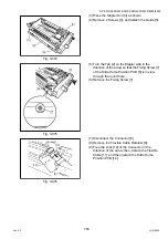
1) Set SW1 on the Finisher Controller PCB as follows :
Fig. 5-003
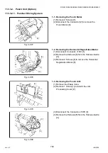
2) Adjust the stapling position by pressing the PSW1 or PSW2 on the Finisher Controller PCB a
required number of times. Pressing the switch once moves the stapling position about 0.14mm.
• To move the stapling position in the "-" direction, press the PSW1.
• To move the stapling position in the "+" direction, press the PSW2.
• Turn on Points 1, 4 of SW1 on the circuit board first and then press the PSW1 and PSW2 at the
same time clears the adjustment value.
Fig. 5-004
3) When adjustment of the stapling position is complete, set all bits of the SW1 on the Finisher
Controller PCB to OFF.
4) Enter the bind mode of the Host Machine and check whether the stapling position is adjusted
properly. If adjusted improperly, adjust the stapling position again.
ON
1
2
3
4
5
6
7
8
- direction
+ direction
Summary of Contents for DP-3530
Page 4: ...4 Beispiel DP 6530 4530 6030 Hinweis ...
Page 424: ...424 JAN 2006 Ver 5 2 DP 3510 3520 3530 4510 4520 4530 6010 6020 6030 ...
Page 425: ...425 JAN 2006 Ver 5 2 DP 3510 3520 3530 4510 4520 4530 6010 6020 6030 ...
Page 474: ...474 JAN 2006 Ver 5 2 DP 3510 3520 3530 4510 4520 4530 6010 6020 6030 memo ...
Page 842: ...memo ...
Page 858: ...DZZSM00298 ...


