background image

ANUP5204 Aicure   

Assembly 


13 


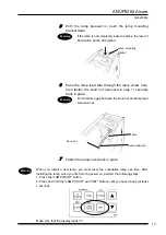
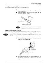
With the lamp pressed in, push the lamp mounting 
bracket down.   

If the lamp is not completely locked in place, the level of 
illumination will be diminished.   


Pass the lamp lead wire through the lamp screw hole, 
then fasten the knurl nut (removed in step 1) securely 
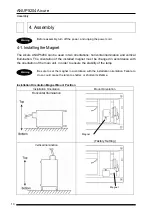
back in place.   

Do not allow a gap between the knurl nut and lamp lead 
wire terminal. 


Fasten the lamp cover back in place.   


When you install a new lamp, you must reset the cumulative lamp use time. After 
installing the lamp, when you first turn the power on, perform the following steps: 

1. Press the "LAMP HOUR" button.   
2. Press and hold the "LAMP HOUR" and "SET" buttons until you hear a beep (at least 
1 second).   


Make sure that the display reads "0". 

Warning


Warning


Lamp mounting

bracket 

Lamp 

Knurl nut 

Lamp lead wire 

Warning


Summary of Contents for ANUP5204

Page 1: ...Matsushita Electric Works Machine Vision Ltd ANUP5204 Aicure UV Curing System User s Manual ...

Page 2: ... high voltage Avoid operating the device with charged parts exposed or repairing or calibrating the device with the power turned on Doing so could cause electric shock Always earth the system Failure to do so could cause electric shock Make sure the lamp is completely cooled about 30 min or more after the lamp is turned off then remove the cover before replacing the lamp While the lamp is on and i...

Page 3: ...hange its internal cooling conditions causing damage due to overheating If two systems are used back to back exhaust could cause damage due to overheating 7 Do not leave the lamp on for prolonged periods while the cover is off Doing so could cause the lamp or system to overheat and break 8 In order to avoid lighting failures due to overcooling attach the light guide fiber unit to the jack on the f...

Page 4: ...n Irradiation 20 UV Intensity Setting 20 UV Autocontrol Feature 21 Setting Lock Feature 21 Counter Feature 21 8 Irradiation 22 8 1 Manual Irradiation 22 8 2 Timer Irradiation 25 8 3 Pattern Irradiation patterns 0 to 9 27 9 Operation via External Signals 32 9 1 How the External Control Connector and Signals Work 32 9 2 Operating via External Signals 34 Manual Irradiation 34 Timer Irradiation 34 Pat...

Page 5: ...th the qualities of the material to cure will prevent curing shrinkage and warping in optical products and the like Changing UV intensity externally You can change the UV intensity externally as you like You can also combine with the UV sensor to perform UV light feedback control Digital display with no individual differences Every item that requires it can be configured and displayed using easy t...

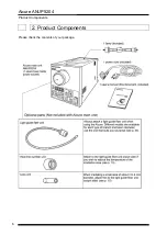
Page 6: ...Aicure ANUP5204 Product Components 6 2 Product Components Please check the contents of your package Product Components ...

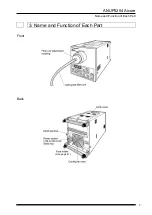
Page 7: ...ANUP5204 Aicure Name and Function of Each Part 7 3 Name and Function of Each Part Front Back See page 41 ...

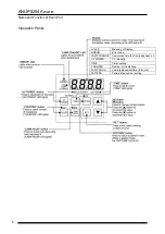
Page 8: ...ation Panel Lit LED Meaning of Display ERROR Error code LAMP CHANGE Cumulative time that lamp has been on UV POWER UV intensity TIME Timer setting COUNTER Number of irradiations LAMP HOUR Lamp replacement time in hours PATTERN Pattern step number setting ...

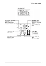
Page 9: ...ANUP5204 Aicure Name and Function of Each Part 9 ...

Page 10: ...talled magnet must be changed in accordance with the orientation of the main unit in order to ensure the stability of the lamp Be sure to set the magnet in accordance with the installation orientation Failure to do so could cause the lamp to shatter or shorten its lifetime Installation Orientation Magnet Mount Position Installation Orientation Mount Orientation Horizontal Illumination Factory Sett...

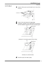
Page 11: ...1 bolt and remove the magnet plate 3 Change the orientation of the magnet plate in accordance with the installation orientation then lock it in place again Orientation for horizontal illumination factory setting Orientation for vertical illumination 4 Mount the lamp cover back in place Lamp cover Magnet plate Magnet plate ...

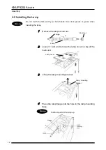
Page 12: ...when installing the lamp 1 Remove the lamp s knurl nut 2 Loosen 1 bolt and remove the lamp cover on top of the main unit 3 Lift up the lamp mounting bracket 4 Press the lamp flange into the hole in the lamp mounting base Put the A part of the lamp up Warning Lamp cover Lamp Knurl nut Lamp mounting bracket Warning A Flange ...

Page 13: ...place Do not allow a gap between the knurl nut and lamp lead wire terminal 7 Fasten the lamp cover back in place When you install a new lamp you must reset the cumulative lamp use time After installing the lamp when you first turn the power on perform the following steps 1 Press the LAMP HOUR button 2 Press and hold the LAMP HOUR and SET buttons until you hear a beep at least 1 second Make sure th...

Page 14: ...UV intensity attach a lens unit optional to the irradiation outlet of the light guide fiber unit To reduce the temperature of the irradiation unit attach a heat ray blocking filter optional to the irradiation inlet of the light guide fiber unit Installing the light guide fiber unit 1 Loosen the bolt on the fiber unit mounting inlet on the front of the main unit 2 Press the light guide fiber unit i...

Page 15: ...ol Installing the UV blocking filter optional Use a heat ray blocking filter unit to reduce the temperature of the irradiation unit This unit passes through short wavelength radiation 254 to 436 nm and blocks heat rays greater than this Mount the heat ray blocking filter before attaching the light guide fiber unit to the Aicure main unit 1 Screw the heat ray blocking filter all the way onto the li...

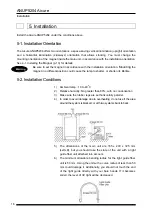
Page 16: ...lamp to shatter or shorten its lifetime 5 2 Installation Conditions 1 Ambient temp 10 to 40 o C 2 Relative humidity No greater than 80 with no condensation 3 Make sure the rubber legs are set horizontally parallel 4 In order to avoid damage due to overheating do not use if the area around the system is blocked or with two systems back to back 5 The dimensions of the main unit are 165 x 200 x 325 m...

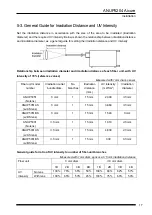
Page 17: ...es Measured with 1mm diam sensor Fiber unit model number Irradiation outlet bundle diam No branches Irradiation distance mm UV intensity mW cm2 Irradiation diameter ANUP5051 No lens 5 mm 1 15 mm 2 300 3 5 mm ANUP5051AS w AS lens 5 mm 1 15 mm 3 860 3 5 mm ANUP5051BS w BS lens 5 mm 1 15 mm 1 540 5 mm ANUP5031 No lens 3 5 mm 1 15 mm 1 310 4 5 mm ANUP5031AS w AS lens 3 5 mm 1 15 mm 4 830 2 5 mm ANUP50...

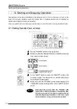
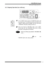
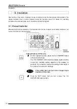
Page 18: ...tion turn on lamp 1 Set the POWER switch in the up position 2 Make sure that the display reads the cumulative lamp use time and you hear a beep 3 In the LAMP section press the ON OFF button until you hear a beep The lamp turns on and the LED above the ON OFF button lights 4 Make sure that the STABLE lamp stable display and COOLING lamp cooling LEDs in the LAMP section are lit Wait about 30 seconds...

Page 19: ...he lamp turns off the LED above the ON OFF button and the STABLE LED turn off and the COOLING LED lamp cooling remains on 2 Make sure that the COOLING LED in the LAMP section goes off The COOLING LED will be on while the lamp is cooling about 20 minutes Never turn off the power while the COOLING LED is on 3 Set the POWER switch in the down position Warning ...

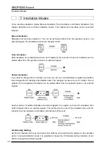
Page 20: ...on If you need to change the UV intensity over time you can do so automatically by registering a pattern that changes the UV intensity and irradiation time The changes can be set in up to 10 steps Up to 9 patterns can be registered Irradiation can be started either from the operation panel or via external signals Another manner of pattern irradiation via external signals is to register up to four ...

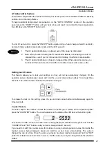
Page 21: ...nter Feature A count is kept of the number of times the shutter is opened up to 9 999 On the operation panel press the COUNTER button The count appears on the display the LED above the button lights To reset the counter while the counter value is being displayed simultaneously press and hold the COUNTER and SET buttons until you hear a beep at least 1 second If you need to modify the counter value...

Page 22: ...n The irradiation time can be changed at will Before irradiation set and or check the UV intensity setting Setting Checking UV Intensity 1 On the operation panel press the UV POWER button until you hear a beep The UV POWER LED under the display lights and the current UV intensity setting appears in the display in percent If you need to change the setting follow steps 2 to 4 below to set the UV int...

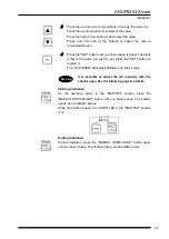
Page 23: ...ess the SET button to register it The UV POWER LED stops flashing and lights solidly It is possible to adjust the UV intensity with the shutter open See the following page for details Starting Irradiation On the operation panel in the SHUTTER section press the MANUAL OPEN CLOSE button until you hear a beep The shutter opens and irradiation begins While the shutter is open the OPEN LED in the SHUTT...

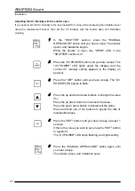
Page 24: ... a beep The UV POWER LED lights under the display and the current UV intensity setting appears in the display in percent 3 Press the SET button until you hear a beep The UV POWER LED begins to flash 4 Press the up and down arrow buttons to change the value Press the up arrow button to increment the value Press the down arrow button to decrement the value Press and hold one of the buttons to speed ...

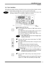
Page 25: ...econds If you need to change the setting follow steps 2 to 4 below to set the timer value If the setting does not need to be changed begin irradiation in this state 2 Press the SET button until you hear a beep The TIME LED begins to flash 3 Press the up and down arrow buttons to change the value seconds Press the up arrow button to increment the value Press the down arrow button to decrement the v...

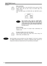
Page 26: ...oses automatically If you press the button again irradiation stops before the time runs out Ending Irradiation After the set time passes the shutter closes automatically and irradiation ends Stopping Irradiation before the Time Elapses Press the AUTO START button again until you hear a beep The shutter closes and irradiation ends Manual irradiation is given precedence over timer irradiation For th...

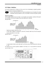
Page 27: ...u can register patterns of up to 10 steps You can register up to 9 patterns numbered 0 through 8 For each step you can set an irradiation time timer value and UV intensity Sample Pattern 1 Steps are executed in order from 0 to 9 At each step irradiation is performed at the set UV intensity After the set time has elapsed execution proceeds to the next step Sample Pattern 2 To end irradiation before...

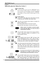
Page 28: ... SET button until you hear a beep at least 1 second Subsequent settings are performed on the selected pattern number Set Each Step 5 On the operation panel press the SET and down arrow buttons simultaneously until you hear a beep at least 1 second The TIME LED under the display begins to flash and the step number and timer value appear in the display 6 Press the up and down arrow buttons to change...

Page 29: ... register it Once a step is registered the system moves to the next step setting automatically The UV POWER LED goes out and the TIME LED under the display begins to flash The step number and timer value appear in the display 10 Repeat steps 6 through 9 for the following steps Register steps 0 through 9 After step 9 has been registered step setup ends automatically To end irradiation before step 9...

Page 30: ...nd Subsequent settings are performed on the selected pattern number 5 Press the SET button on the operation panel and the down arrow button until you hear a beep at least 1 second If this is the value you wish to set press the SET button to register it The UV POWER LED begins to flash The step number and UV intensity appear in the display 6 Press the up and down arrow buttons to change the value P...

Page 31: ...Register steps 0 through 3 After step 3 has been registered step setup ends automatically When you end the step setting the display returns to the pattern number To quit from step setting midway press the up and down arrow buttons simultaneously or wait for one minute or more Warning ...

Page 32: ... and the pattern number appears in the display Select a Pattern Number 2 Press the SET button until you hear a beep at least 1 second The LED above the PATTERN button begins to flash 3 Press the up and down arrow buttons to change the pattern number 0 to 8 Press the up arrow button to increment the value Press the down arrow button to decrement the value Pattern number 9 is available via external ...

Page 33: ...radiation After the entire pattern that was set ends the shutter closes automatically and irradiation ends To Forcibly End Irradiation Midway During Pattern Irradiation Press the AUTO START button again until you hear a beep The shutter closes and irradiation ends The pattern mode is retained even if the power is interrupted It is not necessary to switch to pattern mode or select pattern numbers e...

Page 34: ... connection Output Pin No Signal Name I O Polarity What the signal does 1 LAMP ON Output On when LAMP ON OFF LED lit 3 LAMP STABLE Output On when LAMP STABLE LED lit 4 SHUTTER OPEN Output On when SHUTTER OPEN LED lit 5 SHUTTER CLOSE shutter closed Output On when SHUTTER OPEN LED off 7 LAMP CHANGE Lamp change time Output On when LAMP CHANGE LED lit 8 ERROR Output On when ERROR LED lit 16 24 Use whe...

Page 35: ...0 3 sec 12 LAMP START Input Lamp is one while signal is being input 13 GND G GND 14 IRIS OPEN Input Each time a single Normal Mode signal is input the UV intensity setting is increased 0 5 if pulse is on for at least 0 3 sec off for at least 0 3 sec 1 15 IRIS CLOSE Input Each time a single Normal Mode signal is input the UV intensity setting is decreased 0 5 if pulse is on for at least 0 3 sec off...

Page 36: ...rradiation The irradiation time can be changed at will see p 22 Operate the POWER switch from the operation panel Timer Irradiation Start irradiation at a predetermined time and irradiate for the amount of time set see p 25 Operate the POWER switch and set the irradiation time timer value from the operation panel Warning Warning ...

Page 37: ...tterns 0 to 8 If you need to change the UV intensity over time you can do so automatically by registering a pattern that changes the UV intensity and irradiation time see p 27 Operate the POWER switch and switch to pattern mode set patterns from the operation panel Warning ...

Page 38: ... changed in accordance with the state of the work Operate the POWER switch and switch to pattern mode set pattern 9 from the operation panel see pp 27 29 For pattern 9 only set the UV intensity for steps 0 to 3 Use pin 9 MANUAL START signal to start and stop irradiation and pins 14 and 15 to select steps 0 to 3 Step Number Selection Step No Pin 14 IRIS OPEN Pin 15 IRIS CLOSE 0 OFF OFF 1 OFF ON 2 O...

Page 39: ...the display 2 On the operation panel press the SET button until you hear a beep at least 1 second The LED above the LAMP HOUR button flashes and the lamp replacement alarm time appears in the display 3 Press the up and down arrow buttons to change the value hours Press the up arrow button to increment the value Press the down arrow button to decrement the value Press and hold one of the buttons to...

Page 40: ...wer cord before starting work in order to allow the lamp to cool Replace the lamp when its lifetime is reached After replacing the lamp you must reset the cumulative lamp use time 11 1 Replace the Lamp Do not touch the lamp with your bare hands Use clean gloves or gauze when installing the lamp 1 Remove the lamp s replacement knurl nut 2 Loosen 1 bolt and remove the lamp cover on top of the main u...

Page 41: ...eplacement lamp lead wire through the lamp screw hole then fasten the knurl nut removed in step 1 securely back in place 8 Replace the lamp cover and lock it in place Do not allow a gap between the knurl nut and lamp lead wire terminal When you install a new lamp you must reset the cumulative lamp use time After installing the lamp when you first turn the power on perform the following steps 1 Pre...

Page 42: ...ower cord before starting work 1 Loosen 1 bolt and remove the lamp cover on top of the main unit 2 Remove 7 bolts and remove the main unit cover 3 With the lamp mounting bracket pulled down remove the knurl screw and remove the lead wire from the lamp Also after removing the screw to free the dividing plate remove the high voltage screw and remove the plus lead 4 Remove the old lead wire from the ...

Page 43: ...t protection 4 If the lamp voltage exceeds the maximum limit over time the lamp will shut off 5 When an external terminal is connected the control circuit will stop if 24V and GND are mistakenly shorted 12 2 Replacing the Fuse A spare fuse is kept in the power socket If the fuse blows replace it with the spare When removing the fuse from the fuse holder be careful not to apply excessive force to t...

Page 44: ...not light stably if it is lit without one attached 2 Is the magnet installed with the same orientation as the system 3 Has the lamp reached its lifetime UV intensity too weak 1 Is the lamp loose 2 Is there fine dust or debris where the lamp is installed Note Take out the lamp and check 3 Has the lamp reached its lifetime 4 Is the light guide fiber unit tip or lens soiled Note If it is soiled wipe ...

Page 45: ...ontrol connector LAMP STABLE signal pin 3 off ERROR signal pin 5 on Reset Error Status Press and hold the SET button until you hear a beep at least 1 second The alarm buzzer stops Note however that the error display will not clear until the cause of the abnormality has been dealt with and the lamp will not come on See the following page for measures to take in the event of abnormalities After taki...

Page 46: ...amp E20 The shutter does not recover to its origin position after the prescribed length of time E21 The shutter won t close E22 The shutter won t open E23 The shutter is out of alignment E24 The shutter does not recover to its origin position normally 1 Reset the error status If the error code display does not clear after resetting flip the power to off then back on 2 Referring to p 40 check if th...

Page 47: ...eature also allows you to freely select from 4 preset UV intensities via external signals pattern number 9 Setting Lock This feature prevents values from changing On the operation panel simultaneously press and hold the up and down arrow buttons for at least three seconds to lock or release the settings Features Counter This feature automatically counts the number of times the shutter opens This c...

Page 48: ...ANUP5204 Aicure Dimension Drawing 48 15 Dimension Drawing 25 30 ...

Page 49: ...cording to your needs Irradiation side bundle diam 5 mm 3 5 mm and 8 mm Num branches 1 to 4 Spare Parts We recommend keeping them on hand at all times Part Specifications Order Part Number Lamp Preset 200W mercury xenon lamp Lifetime 3 000 hours ANUPS204 Positive lamp lead wire positive side lead wire Special heat resistant positive side lamp electrical wire ANUHP5204W Shutter motor Stepping motor...

Page 50: ...ued Revision Details 2003 04 01 Initial version 2004 08 Second revision Although our manuals are prepared with great care if you should spot any errors please let us know at the address below Matsushita Electric Works Machine Vision Ltd 1048 Kadoma Kadoma City Osaka 571 8686 Japan ...

Reviews: