


3-18
Machine Maintenance Procedures
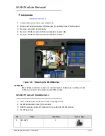
5.
Insert narrow tool into hole (G) on bezel, to eject module (A) from tray (Figure 3-13).
6.
Press down on latch (H) to unlock bezel (F) from module (A).
7.
Remove bezel (F) from module.
Figure 3-13.
ODD Module
ODD Module Installation
0
1.
Connect bezel (F) to module. Refer to Figure 3-12.
2.
Attach and secure bracket (C) to module with two (2) screws (B).
3.
Insert module (A) into module bay. Refer to
Figure 3-11
.
4.
Install base door.
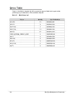
ID
Size
Quantity
Screw Type
B
M1.98*3
2
F
G
A
H
Summary of Contents for EasyNote LS11HR
Page 1: ...Packard Bell EasyNote LS11HR LS13HR SERVICEGUIDE ...
Page 10: ...x ...
Page 11: ...CHAPTER 1 Hardware Specification ...
Page 14: ...1 4 ...
Page 55: ...CHAPTER 2 System Utilities ...
Page 77: ...CHAPTER 3 Machine Maintenance ...
Page 80: ...3 4 ...
Page 123: ...CHAPTER 4 Troubleshooting ...
Page 149: ...CHAPTER 5 Jumper and Connector Locations ...
Page 156: ...5 8 Jumper and Connector Locations ...
Page 157: ...CHAPTER 6 FRU List ...
Page 158: ...6 2 Exploded Diagrams 6 4 FRU List 6 6 Screw List 6 20 ...
Page 177: ...CHAPTER 7 Model Definition and Configuration ...
Page 178: ...7 2 Packard Bell EasyNote LS11HR LS13HR 7 3 ...
Page 202: ...7 26 Model Definition and Configuration ...
Page 203: ...CHAPTER 8 Test Compatible Components ...
Page 204: ...8 2 Microsoft Windows 7 Environment Test 8 4 ...
Page 214: ...8 12 Test Compatible Components ...
Page 215: ...CHAPTER 9 Online Support Information ...
Page 216: ...9 2 Introduction 9 3 ...
Page 218: ...9 4 Online Support Information ...