


6-4
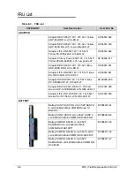
FRU (Field Replaceable Unit) List
Exploded Diagrams
0
Figure 6-1.
Main Assembly Exploded Diagram
Table 6-1.
Main Assembly Exploded Diagram
No.
Description
Acer Part No.
No.
Description
Acer Part No.
1
Keyboard
KB.I170G.292
5
Speakers
23.RB002.003
2
Upper Cover
60.BRD02.001
6
USB Board
55.RB002.002
3
Mainboard
MB.RB002.001
7
LAN Board
55.RB002.005
4
Thermal Module
60.RB002.013
8
Lower Cover
60.BRD02.003
1
2
3
4
5
6
7
8
Summary of Contents for EasyNote LS11HR
Page 1: ...Packard Bell EasyNote LS11HR LS13HR SERVICEGUIDE ...
Page 10: ...x ...
Page 11: ...CHAPTER 1 Hardware Specification ...
Page 14: ...1 4 ...
Page 55: ...CHAPTER 2 System Utilities ...
Page 77: ...CHAPTER 3 Machine Maintenance ...
Page 80: ...3 4 ...
Page 123: ...CHAPTER 4 Troubleshooting ...
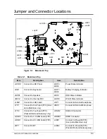
Page 149: ...CHAPTER 5 Jumper and Connector Locations ...
Page 156: ...5 8 Jumper and Connector Locations ...
Page 157: ...CHAPTER 6 FRU List ...
Page 158: ...6 2 Exploded Diagrams 6 4 FRU List 6 6 Screw List 6 20 ...
Page 177: ...CHAPTER 7 Model Definition and Configuration ...
Page 178: ...7 2 Packard Bell EasyNote LS11HR LS13HR 7 3 ...
Page 202: ...7 26 Model Definition and Configuration ...
Page 203: ...CHAPTER 8 Test Compatible Components ...
Page 204: ...8 2 Microsoft Windows 7 Environment Test 8 4 ...
Page 214: ...8 12 Test Compatible Components ...
Page 215: ...CHAPTER 9 Online Support Information ...
Page 216: ...9 2 Introduction 9 3 ...
Page 218: ...9 4 Online Support Information ...