


Machine Maintenance Procedures
3-15
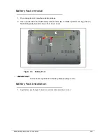
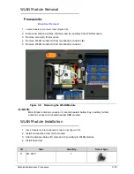
WLAN Module Removal
0
Prerequisite:
Base Door Removal
1.
Locate module (A) on lower cover (Figure 3-9).
2.
Disconnect antenna cables, (B) main and (C) auxiliary from WLAN module.
3.
Remove screw (D) from module.
4.
Remove WLAN module (A) from mainboard connector (E).
5.
Remove WLAN module (A) from mainboard connector.
Figure 3-9.
Removing the WLAN Module
NOTE:
NOTE
:
Main (black) antenna connector is located nearest battery bay. Auxiliary (white)
antenna connector is located nearest HDD module.
WLAN Module Installation
0
1.
Insert module (A) into mainboard connector (E) (Figure 3-9).
2.
Install and secure screw (D) to module.
3.
Attach antenna cables, (B) main and (C) auxiliary to WLAN module.
4.
Install base door.
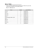
ID
Size
Quantity
Screw Type
D
M1.98*3
1
D
B
C
A
E
Summary of Contents for EasyNote LS11HR
Page 1: ...Packard Bell EasyNote LS11HR LS13HR SERVICEGUIDE ...
Page 10: ...x ...
Page 11: ...CHAPTER 1 Hardware Specification ...
Page 14: ...1 4 ...
Page 55: ...CHAPTER 2 System Utilities ...
Page 77: ...CHAPTER 3 Machine Maintenance ...
Page 80: ...3 4 ...
Page 123: ...CHAPTER 4 Troubleshooting ...
Page 149: ...CHAPTER 5 Jumper and Connector Locations ...
Page 156: ...5 8 Jumper and Connector Locations ...
Page 157: ...CHAPTER 6 FRU List ...
Page 158: ...6 2 Exploded Diagrams 6 4 FRU List 6 6 Screw List 6 20 ...
Page 177: ...CHAPTER 7 Model Definition and Configuration ...
Page 178: ...7 2 Packard Bell EasyNote LS11HR LS13HR 7 3 ...
Page 202: ...7 26 Model Definition and Configuration ...
Page 203: ...CHAPTER 8 Test Compatible Components ...
Page 204: ...8 2 Microsoft Windows 7 Environment Test 8 4 ...
Page 214: ...8 12 Test Compatible Components ...
Page 215: ...CHAPTER 9 Online Support Information ...
Page 216: ...9 2 Introduction 9 3 ...
Page 218: ...9 4 Online Support Information ...


