


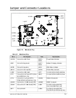


Jumper and Connector Locations
5-7
BIOS Recovery by Crisis Disk
0
BIOS Recovery Boot Block
0
BIOS Recovery Boot Block is a special block of BIOS. It is used to boot up the system with
minimum BIOS initialization. Users can enable this feature to restore the BIOS firmware to a
successful one once the previous BIOS flashing process failed.
BIOS Recovery Hotkey
0
The system provides a function hotkey, <
Fn+Esc
>
, for enable BIOS Recovery process when
system is powered on during BIOS POST. To use this function, it is strongly recommended to
have the AC adapter and Battery present. If this function is enabled, the system will force the
BIOS to enter a special BIOS block, called Boot Block.
Steps for BIOS Recovery from USB Storage
0
NOTE:
NOTE
:
Prior to performing the recovery, prepare a Crisis USB key. The Crisis USB key is
created by executing the Crisis Disk program in another system with Windows 7 OS.
To Create a Crisis USB key, perform the following:
1.
Format the USB storage disk using the Fast Format option.
2.
Save KBC and BIOS into one file. The command to do so is:
< copy /b KBC.ROM + BIOS.FD P5WE0x64.fd >
Figure 5-5.
Creating P5WE0x64.fd file
3.
Save ROM file (file name:
P5WE0x64.fd
) to the root directory of USB storage. Make sure
that there is no other BIOS file saved in the same directory.
4.
Plug USB storage into USB port.
5.
Press <
Fn+ESC
>
button then plug in AC power.
6.
The Power button flashes once.
7.
Press
Power
button to initiate system CRISIS mode.
8.
When CRISIS is complete, the system auto restarts with a workable BIOS.
9.
Update the latest version BIOS for this machine by regular BIOS flashing process.
Summary of Contents for EasyNote LS11HR
Page 1: ...Packard Bell EasyNote LS11HR LS13HR SERVICEGUIDE ...
Page 10: ...x ...
Page 11: ...CHAPTER 1 Hardware Specification ...
Page 14: ...1 4 ...
Page 55: ...CHAPTER 2 System Utilities ...
Page 77: ...CHAPTER 3 Machine Maintenance ...
Page 80: ...3 4 ...
Page 123: ...CHAPTER 4 Troubleshooting ...
Page 149: ...CHAPTER 5 Jumper and Connector Locations ...
Page 156: ...5 8 Jumper and Connector Locations ...
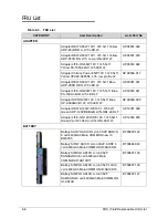
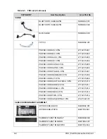
Page 157: ...CHAPTER 6 FRU List ...
Page 158: ...6 2 Exploded Diagrams 6 4 FRU List 6 6 Screw List 6 20 ...
Page 177: ...CHAPTER 7 Model Definition and Configuration ...
Page 178: ...7 2 Packard Bell EasyNote LS11HR LS13HR 7 3 ...
Page 202: ...7 26 Model Definition and Configuration ...
Page 203: ...CHAPTER 8 Test Compatible Components ...
Page 204: ...8 2 Microsoft Windows 7 Environment Test 8 4 ...
Page 214: ...8 12 Test Compatible Components ...
Page 215: ...CHAPTER 9 Online Support Information ...
Page 216: ...9 2 Introduction 9 3 ...
Page 218: ...9 4 Online Support Information ...