


35
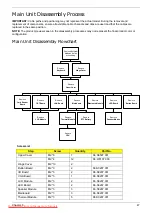
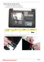
External Module Disassembly Process
NOTE:
The product previews seen in the disassembly procedures may not represent the final product color or
configuration.
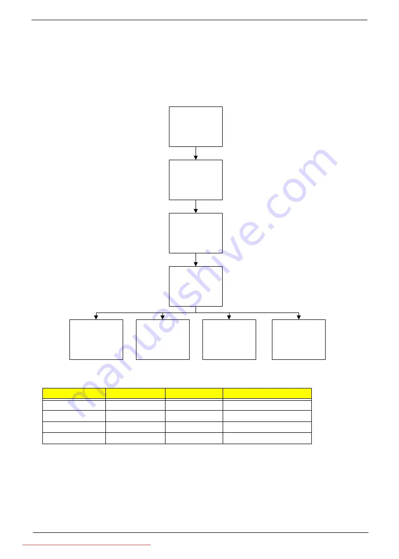
External Modules Disassembly Flowchart
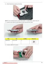
Screw List
Step
Screw
Quantity
Part No.
HDD Carrier
M3*0.5+3.5I
4
86.TDY07.003
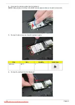
WLAN Board
M2*3
1
86.S0207.001
HDD Module
M2*3
2
86.S0207.001
3g Card
M2*3
2
86.S0207.001
Disconnect power
and signal cables
from system
Remove
Battery
Turn off system
and peripherals
power
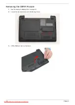
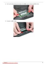
Remove
DIMM
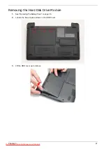
Remove
HDD
Remove
Lower Covers
Remove
WLAN Board
Remove
3g Board
Summary of Contents for DOTMA-111G16i
Page 6: ...VI Downloaded from LpManual com Manuals ...
Page 10: ...X Table of Contents Downloaded from LpManual com Manuals ...
Page 54: ...44 Chapter 3 6 Remove the WLAN Board from the Mainboard Downloaded from LpManual com Manuals ...
Page 67: ...Chapter 3 57 4 Lift the LED Board from the Lower Cover Downloaded from LpManual com Manuals ...
Page 132: ...122 Chapter 3 Downloaded from LpManual com Manuals ...
Page 154: ...144 Chapter 5 Downloaded from LpManual com Manuals ...
Page 172: ...162 Appendix C Downloaded from LpManual com Manuals ...


