38
THERMAL MANAGEMENT CENTER
POWER UP
1. Insure that the system is properly prepared for
operation. Refer to the “Set-Up” portion of this manual.
The handpieces selected for your application should be
connected to the unit. Connect any single air hose to
either the
SNAP-VAC
Port or Controllable
PRESSURE
Port. Never connect air hoses to both ports
simultaneously. Always leave VisiFilter connected to
SNAP-VAC
Port.
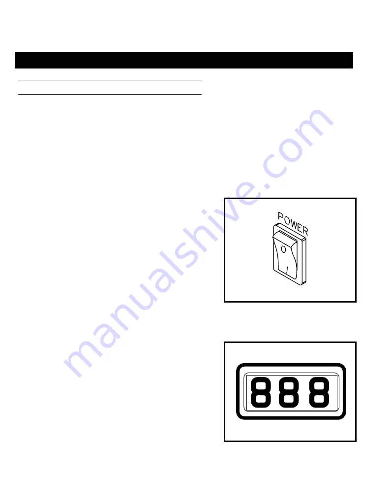
2. Turn the
POWER
Switch ON (“1”).
3. On power up, the Digital Readout will display "888"
initially; change to "1 - 3" (this number may be different
on your system) and then display normal temperature
information (Temperature Display Mode).
Figure 24. Power On
Figure 25. Digital Readout "888"
Summary of Contents for PRC 2000
Page 1: ...1 SYSTEM OPERATION MAINTENANCE MANUAL PRC 2000 SYSTEMS ...
Page 2: ...2 ...
Page 3: ...3 MANUAL NO 5050 0313 REV G ...
Page 17: ...17 Figure 6 Thermal Management Center ...
Page 23: ...23 Figure 12 Pik And Paste Section ...
Page 74: ...74 ...
Page 95: ...95 Figure 122 Pulse Plate Set Up ...
Page 96: ...96 ...
Page 102: ...102 ...
Page 111: ...111 ...
Page 119: ...119 ...


