OSF WATERFRIEND MRD-3 Installation And Operating Instructions Manual Download Page 17

 Installation and operating manual for WATERFRIEND -Chlorine     MRD-3      Page 17 

The  use-by  date  must  be  observed  for  the  buffer  solutions  The  solutions  must  always  be  stored  in  a  cool, 
dark place. Buffer solutions may not be soiled during use. For this reason, electrodes may not be immersed 
in different buffer solutions successively without cleaning them with distilled water first. It is also important not 
to  rub  the  electrodes  with  a  cloth,  because  this  causes  static  charging  and  incorrect  measurements.  The 
necessary 

 buffer solutions for pH 4, pH 7 and for ORP 468mV and 

 spare electrodes are available 

from the 

 "WATERFRIEND“ metering unit supplier. 

The  electrodes  must  be  free  of  impurities,  oils  and  fats  etc  before  they  are  inserted  in  the  flow  fittings. 
Furthermore,  the  diaphragms  (small  spots  at  the  probe  point)  must  be  free  of  coatings,  soiling  and 
crystallisation deposits. Do not touch the glass body with your hands to avoid impurities. 

The calibration is carried out as a 2-point calibration with 2 buffer solutions. These buffer solutions must be 
free of impurities and fresh. 

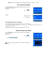
During  the  calibration,  the  measured  electrode  value  and  the  pH  values  for  the  buffer  solutions  set  are 
shown in the display. You can use these displayed values to ascertain the quality of the electrode during the 
calibration. 

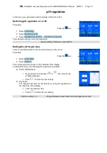
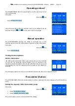
Calibrating the upper value (pH 7) 

Procedure: 

 Press the 

 key 

1.  Select pH settings 

2.  Select Calibration 

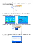
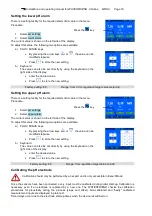
In  the  first  stage,  the  upper  point  (pH  7)  is  calibrated.  To  do  this,  the  pH  electrode  is  immersed  in  a  buffer 
solution of pH 7. The current values for the pH electrode are then shown  in the  display. When the value in 
the display does not change any more, you can either 

select end calibration 


or 

Single-point calibration (pH): 

The  calibration  is  complete.  The  offset  value  is 
accepted and stored 

select to 2. point 

Two-point calibration (pH): 

Continue to calibration of lower value (pH 4) 

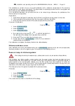
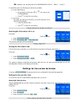
Calibrating the lower value (pH 4) 

In the second stage, the lower point (pH 4) is calibrated. To do this, the pH electrode (which must have been 
cleaned  in  distilled  water  first)  is  immersed  in  a  buffer  solution  of  pH  4.  The  current  values  for  the  pH 
electrode are then shown in the display. When the value in the display does not change any more, press end 

calibration to store the new offset and slope values of the sensor. 

Caution:  It  is  also  important  not  to  rub  the  electrode  with  a  cloth,  because  this  causes  static  charging  and 
incorrect measurements.
 

Once calibration is complete, the slope and offset of the electrode are shown in the display. 

If  the  offset  difference  falls  below  a  value  of  ±  60mV,  the  calibration  cannot  be  correctly  completed.  The 
display shows the message Big divergence. 

The  slope  must  be  in  a  range  between  45.0  and  65.0  mV.  If  not,  the  calibration  cannot  be  correctly 
completed. The display shows the message Big divergence. 

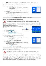
If the electrode values are outside specific tolerances, a message is shown to alert you to this fact. If this is 
the case, the electrode should be replaced as soon as possible. 

pH calibration errors 

If the calibration was not able to be completed and the  Big divergence is shown in the display, the following 
causes are possible: 


The pH electrode (combination electrode) is worn. The electrode service life is limited depending on 
the water quality and its care. 


You  have  mixed  up  the  buffer  solution  sequence  (1st  pH  7,    2nd  pH  4).  This  sequence  must  be 
strictly observed. 


You used the same buffer solution twice. Correct calibration can only be carried out with two different 
buffer solutions. 

Summary of Contents for WATERFRIEND MRD-3

Page 1: ...ltage Metering pump pH Metering pump chlorine Protection class Housing size IP 20 625 x 390 x 130 Humidity Ambient temperature 0 to 40 C Metering pump flocculation option 0 bis 10 l h 1 N PE 230V 50Hz...

Page 2: ...cation server 9 Read device ID on the display of the dosing control 10 Touchpanel 11 Temperature 11 Measurement water flow quantity 11 Display 12 Analog display 12 Initial setup 13 Select language 13...

Page 3: ...6 Setting the upper ORP alarm 27 Setting the ORP power on delay 27 Calibrating the ORP electrode 28 ORP calibration errors 28 Info and alarm display 29 Acknowledgement of alarm messages 29 Graph of me...

Page 4: ...chscreen calibration 36 Calibration of the temperature sensor 37 Additional settings via the LAN interface 37 Maintenance 38 6 monthly service 38 Sealtightness 38 Dirt filter 38 Injection valves 38 pH...

Page 5: ...controller Gas emitting chemicals can cause damage to the sensitive controller Personnel qualification The personnel who will be operating maintaining inspecting and installing the device must have a...

Page 6: ...ction power failure or a defective metering system may not cause any consequential loss Mounting The bottom housing section is fixed vertically and permanently to a solid wall with suitable load beari...

Page 7: ...cessarily long hose lengths Hoses may not be routed directly over pipes carrying heat or over other devices Electrical connection The controller must be mounted protected against moisture in accordanc...

Page 8: ...External pumps These connecting terminals are control contacts for external metering pumps The terminals can be loaded with maximum 230V 1A Enabling At these terminals the dosing enable signal of the...

Page 9: ...usly for the communication server and logs on to the database If the OSF icon in the monitor is visible see chart the WATERFRIEND has logged on to the communication server Using the communication serv...

Page 10: ...appropriate field The DEVICE ID of your device is shown on the device information page on the control panel of the device Read device ID on the display of the dosing control After that your device wil...

Page 11: ...water temperature in the swimming pool depending on the pipeline routing and surrounding temperatures Measurement water flow quantity Quantity of water flowing through the fittings Teh chlorine regula...

Page 12: ...3 Page 12 Display Analog display Setpoint Current value Current pH value Setpoint pH Regulation status Analog display pH Current chlorine value Setpoint chlorine Regulation status Analog display chlo...

Page 13: ...ibited Calibrate the sensors Turn on automatic dosing In order to achieve good water quality it is useful to operate the metering system a few days without automatic dosage before the calibration is p...

Page 14: ...ted adjustment of important operating parameters On delivery this protection function is activated All functions shown in gray on the display are then locked Protection ON no symbol Protection OFF 26...

Page 15: ...value There is a setting facility for the required pH value in the menu Procedure Press the key 1 Select pH settings 2 Select Setpoint The current setpoint is shown on the left side of the display To...

Page 16: ...pH settings 2 Select upper alarm The current value is shown on the left side of the display To adjust this value the following two options are available a PLUS MINUS keys By pressing the arrow keys or...

Page 17: ...re you can either select end calibration or Single point calibration pH The calibration is complete The offset value is accepted and stored select to 2 point Two point calibration pH Continue to calib...

Page 18: ...f the filter pump the pipe length and the filter itself The delay period can if required be adapted to the actual pool size Procedure Press the key 1 Select pH settings 2 Press the key in the key bar...

Page 19: ...in order to adapt the WATERFRIEND to the requirements of the specific swimming pool This value influences the delivery quantity by optimising the pulse width modulation This means that the duty cycle...

Page 20: ...ting Factory setting 1 00 Range 0 1 to 2 0 Impact of the proportional range Adjustment Benefits Disadvantages Diagram Small P range Fast accurate control When switching on an overshoot can occur Wide...

Page 21: ...t Chlorine settings 2 Select Operating mode 3 Select Operation mode OFF or Operation mode Auto The selected setting is stored automatically Factory setting Operation mode AUTO Setting the chlorine tar...

Page 22: ...ct Chlorine settings 2 Select upper alarm The current value is shown on the left side of the display To adjust this value the following two options are available a PLUS MINUS keys By pressing the arro...

Page 23: ...ey end calibration to store the new calibration data and finish the calibration The calibration is complete the display returns to the default display Chlorine calibration errors If the calibration ca...

Page 24: ...he left side of the display To adjust this value the following two options are available a PLUS MINUS keys By pressing the arrow keys or the value can be modified stepwise Press to store the new setti...

Page 25: ...available a PLUS MINUS keys By pressing the arrow keys or the value can be modified stepwise Press to store the new setting b Keyboard The value can also be set directly by using the keyboard on the...

Page 26: ...keyboard on the right side of the display enter the desired value Press to store the new setting Factory setting 1 5 l h Range 0 2 to 10 0 l h ORP display In this menu you can adjust various settings...

Page 27: ...up after a delay period once the power supply has been provided and once external enable has been switched on e g filter control unit This power on delay is necessary because a period specific to the...

Page 28: ...voltage which is present in the water due to oxidising and reducing ions The calibration is carried out as a 1 point calibration with a 468mV buffer solution This buffer solution must be free of impur...

Page 29: ...acoustic fault signal can be switched off by pressing the button If the controller has stopped operation due to an error it can be restarted after resolving the error by pressing the button Automatic...

Page 30: ...Venting the dosing tubes Shock chlorination By pressing the appropriate button each dosing pump can be switched on and off The respective status indicator is to be observed The maximum duration is lim...

Page 31: ...This function makes it possible to vent the flocculant hose with an increased output of1l h Procedure Press the key 1 Select Flocculation settings 2 Select Fill hose 1l h START or STOP The maximum dur...

Page 32: ...it must be set manually with this function Procedure Press the key 1 Select Service functions 2 Select time date 3 Select Manual time setting 4 Use the keys and to set time and date and then confirm w...

Page 33: ...rs are reset to the factory settings This function should only be used by a professional and is only accessible in Expert Mode Procedure Press the key 1 Select Service functions 2 Select Factory setti...

Page 34: ...gs 4 Set the IP addresses required fort he local network manually using the function IP address manually PIN Numbers With this function the PIN numbers for the operation of the device via the network...

Page 35: ...ction the function of the pH pump and the optional third pump can be configured This setting should only be adjusted by a professional and is only accessible in Expert Mode Raise pH lower pH In order...

Page 36: ...prompt with YES Factory setting 3rd pump disabled Bidirectional control for pH pH and pH If the third pump is configured for the function raise pH to implement a bidirectional control of the pH value...

Page 37: ...tered For confirmation press the button Additional settings via the LAN interface The embedded Web server provides additional settings that affect Internet communication To change these settings the w...

Page 38: ...solutions pH7 and pH4 If there are any noticeable variations the electrode should be calibrated or replaced see above in manual Calibrating pH electrode ORP electrode The electrode function is checke...

Page 39: ...flow fitting Metering pumps Rinse out the metering hoses thoroughly with hot water Empty the metering hoses and remove them from the metering pumps Wear parts The following components are wear parts f...

Page 40: ...Installation and operating manual for WATERFRIEND Chlorine MRD 3 Page 40...

Page 41: ...caused by residual contamination This form has been correctly and completely filled out and the device has been shipped in accordance with the statutory requirements If the manufacturer has to carry o...

Page 42: ...Installation and operating manual for WATERFRIEND Chlorine MRD 3 Page 42...

Reviews: